Electro Tech is an online community (with over 170,000 members) who enjoy talking about and building electronic circuits, projects and gadgets. To participate you need to register. Registration is free. Click here to register now.
Welcome to our site! Electro Tech is an online community (with over 170,000 members) who enjoy talking about and building electronic circuits, projects and gadgets. To participate you need to register. Registration is free. Click here to register now.
For normal opamps at the typical frequencies they are used with, no.
However that circuit uses ultra wide band amps for video in a 50 Ohm design circuit.
At various points they may need either termination, impedance matching, damping or attenuation between stages, depending on the overall design & circuit layout.
Plus, the AD811 is a current feedback amplifier intended for video, rather than a conventional opamp.
1) These are very fast OpAmps, characterized and spec'd in 50 ohm system.
2) Lay board out for 0 ohm R's in those positions, and if your required pulse fidelity
not adequate then try various values, starting with recommended per your schematic.
Obviously any connected to ground get left open starting the eval.
3) As an aside obviously PCB layout crucial. Follow datasheet / eval board recommended layout.
Pay particular attention to bypassing C effectiveness at 10 Mhz.
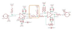
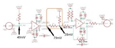
R18 and R19 are each 49.9 ohms so the make a voltage divider (Vout/2). Gain of the second stage is 1.5 so it could saturate without the divider (depending on your input signal voltage).
If the intent is for the combination of R18, R19, and R20 to present to U9, or a transmission line coming it, a 50 ohm termination impedance to GND, then the resistor values are incorrect.
R20 is hard to read. If it is 100 ohms, then the network is 83.3 ohms.
The resistors are forming a 65% attenuator right before a gain stage. Consider this . . .
IF there is no reason for an attenuation pad between U9 and U10,
AND IF the DC levels are compatible with direct coupling into a gain of 10 stage,
THEN Why not delete R18 and R20, connect R19 directly to U10, and increase R21 to 499 ohms? This should get you the same inverting gain of 10, and a 50 ohm termination to (virtual) GND.
Of course, now that the attenuator is gone you probably do not need the full gain of 10. Adjusting the value of R21 to set the gain has no effect on the termination impedance seen by U9.
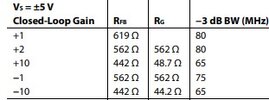
Yes, that is an option as well. I am just following what the datasheet suggests for gain of -10 (442 and 44.2) other wise it is not a requirement to use 44.2
So 49.9 and 499 are within the documented range. Note that the ratio is not strictly 10:1, so while the 49.9 will almost perfectly terminate a transmission line, 499 might not be the correct value for exactly -10x gain.
Note that only one of those resistor pair values is for a gain of -10x.
This site uses cookies to help personalise content, tailor your experience and to keep you logged in if you register.
By continuing to use this site, you are consenting to our use of cookies.