Continue to Site

Welcome to our site!

Electro Tech is an online community (with over 170,000 members) who enjoy talking about and building electronic circuits, projects and gadgets. To participate you need to register. Registration is free. Click here to register now.

  • Welcome to our site! Electro Tech is an online community (with over 170,000 members) who enjoy talking about and building electronic circuits, projects and gadgets. To participate you need to register. Registration is free. Click here to register now.

DIY Resistors Decade Box - Invitation

Status
Not open for further replies.

kiriakos-gr

Member
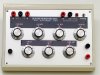
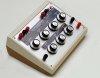
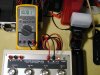
Hello people , I have just finished my own project of one DIY Resistors Decade Box of high precision ...

The project was firstly posted at the EEV-Blog ,
the project looked as very worthy to many,
and it even attracted the interest of the " hackedgadgets ".

So I invite you to visit the " hackedgadgets " and EEV link ,
and post back here any comments or questions ..

Thanks ... Kiriakos Triantafillou - Greece .

DIY Resistors Decade Box - Hacked Gadgets - DIY Tech Blog

EEV - source link ..
Resistors Decade box - How to - Photo story ..
 
I had a 39 year electronic career. I designed and built hundreds of circuits. I designed the circuits using proper electronics and worst case spec's from datasheets. Almost every circuit worked perfectly and only a few needed a resistor value tweaked. So I never needed a resistor decade box.

Do you design circuits without looking at datasheets?
Do you design circuits by "'trial and error"?
 
I knew some egomaniac would come along and trash the project.

Happens ever time I share my projects, that's why I don't do that anymore.
 
First of all a very nice job of the graphics on the panel.

However a few things come to mind.

Looking at your resistance steps I see 1Ω steps and .1mΩ steps. What are the .1mΩ steps? Would they be .0001Ω steps? That would be a little hard to imagine.

You don't mention in what I read the wire gauge(s) used for your internal connections or the importance of using very, very low resistance switches. Each switch in each decade adds contact resistance. That is not a big deal in KΩ steps but can be very important in 1Ω or .1Ω steps just like the wire used.

Another nice touch would have been a complete schematic. Unless I missed it I never saw an overall complete schematic?

Apparently audioguru's 39 year electronic career never had involvement with working with RTD circuits or calibrating RTD circuits where a very good and accurate decade resistance box is an important tool. Matter of fact an indispensable tool. Just one use that comes to mind that I see used daily.

Ron
 
Last edited:
I don't know what kind of precision a decade box typically needs but don't forget that the resistors accuracy rating compounds. If those are .1% resistors and a typical setting as 20 of them you have a worst case possible error of 20%, you'll probably not see quiet that much variation, but it's something to consider, you might have used .01% resistors at least for the larger resistance values.
 
I have to agree with BrownOut. If we look at the attached image we have 10 EA. 100Ω resistors with a tolerance of +/- .1%. The maximum value for any single resistor would be .001 * 100 = .1Ω so if every resistor was 100.1Ω then R total is 1,001 so we are still at an error of .1% for R total. We don't add the error for each resistor and get 1%.

Ron
 

Attachments

  • Resistors Series.gif
    Resistors Series.gif
    7.4 KB · Views: 631
Well I feel silly.
 
Well I feel silly.

LMAO, it's just one of those things. If you take for example a string of instrumentation and need to algebraically add the cumulative errors it can be a pain. :)

Ron
 
Actually, I think you'll find that the statistical error is neither 0.1% or the sum of the worst-case errors in one direction -- it's the square root of the sum of the square of each of the tolerances involved. Each resistor can be expected to be worse-case, but not in the same direction, so things have to average out somewhere. The biggest problem with resistance sub boxes is remembering to stay within the power dissipation of the resistors, which is difficult considering they're inside a box and you can't see the smoke or feel the heat and you're usually in an experimental mode anyway. It's all too easy to kick the resistors in and out such that you end up abusing some of them.
 
The theortical worst case tolerance is .1%

ie

Rtotal = Σ(Ri + Ri*Toli) = ΣRi + ΣRi*Toli

Error = ∑Ri - ∑Ri + ∑Ri*Toli/∑Ri = ΣRi*Toli/ΣRi = Toli. For Toli the same.
 
Last edited:
Thanks for your good words ..

I did corrected the lower label , and so now it looks right .

The pictures was actually snatched from the EEV forum with out my knowledge ,
( it was looking that good ) :)
And I got later on, the information that it was posted publicly.

And so now I have to show again the proofs that I am Innocent :) ( about the small mistake of 0.10 Ohm ) that actually was what was printed on the resistors it self.
 

Attachments

  • decade-final---max-quality-1.jpg
    decade-final---max-quality-1.jpg
    325.5 KB · Views: 339
  • decade-final---max-quality-2.jpg
    decade-final---max-quality-2.jpg
    114.4 KB · Views: 324
  • decade-final---max-quality-3.jpg
    decade-final---max-quality-3.jpg
    268.5 KB · Views: 361
  • 9-completed-zoom-3-DC.jpg
    9-completed-zoom-3-DC.jpg
    86.3 KB · Views: 336
Last edited:
The casework is really nice, very pro !

When some adjustment needs to be done, I usually solder a small pot, tweak it, and then replace it with a resistor of the suitable value. It also has much lower inductance...
 
Well one of many reasons that I feel proud for it , its the success at the inner resistance,
switches and silver plated bridges , gives an 0.04 Ohms ... all seven stages .
And 0.02 the first three ..
 
Well one of many reasons that I feel proud for it , its the success at the inner resistance,
switches and silver plated bridges , gives an 0.04 Ohms ... all seven stages .
And 0.02 the first three ..

Very nice work. Well done.
 
Status
Not open for further replies.

Latest threads

New Articles From Microcontroller Tips

Back
Top