Continue to Site

Welcome to our site!

Electro Tech is an online community (with over 170,000 members) who enjoy talking about and building electronic circuits, projects and gadgets. To participate you need to register. Registration is free. Click here to register now.

  • Welcome to our site! Electro Tech is an online community (with over 170,000 members) who enjoy talking about and building electronic circuits, projects and gadgets. To participate you need to register. Registration is free. Click here to register now.

Design an adjustable voltage switch

Status
Not open for further replies.

stuhagen

Member
I am trying to find away to energize an automotive relay on varying voltage from 0-5V. I want to "fire" the NPN based on adjusting the pot.

This 0-5v is the 0-100% duty of a MAP sensor. I want to be able to make an adjustment so I can control when I want this to switch. Could be anywhere from 0v to its max range of 5v. By adjusting the pot, I want to be able to turn on the relay based on my desired levels.

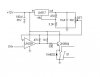
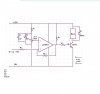
So my thought was to have a adjustable voltage regualtor that has a range of 10v for adjusting. That is where I am a bit confused. Couldnt I just use a 7805, and make that adjustable with a pot for 0-5v? Then the comparator will feed its reference of anywhere from 0-5V, and by adjusting the pot, I can turn on or off the NPN.

It a nutshell, I want to be able to turn on the relay anywheres from 0v to 5v in a linear scale of 0-100%

Stu
 

Attachments

  • MAP circuit design.JPG
    MAP circuit design.JPG
    16.5 KB · Views: 740
hi,
An alternative circuit would be this one.
 

Attachments

  • esp01 Sep. 28.gif
    esp01 Sep. 28.gif
    8 KB · Views: 889
The transistor does not need a resistor in series with its base. The 1k resistor provides it with limited base current.
 
hi,
An alternative circuit would be this one.

Thanks........


Can you help me with values? I have labeled them. So what are the desired values of R1, R2, R3, R4. The "pot" value. I assume the 2N3904 and 1N4002 are OK.
What is a "RLA" ? (relay?) And where is my switching output? Or do I use my original design and take it from the emmitter to ground?

Stu
 

Attachments

  • MAP circuit design-2.JPG
    MAP circuit design-2.JPG
    48.7 KB · Views: 521
If you use a higher power comparator like the LM311, then you don't need a transistor to control the relay providing it uses <50mA.
 
If you use a higher power comparator like the LM311, then you don't need a transistor to control the relay providing it uses <50mA.


I am using a LM311 for a similar project that is still in testing, and that one still needed a TIP31 because the relay requires 1A to turn on, it is 90 ohms accross the coil, and it has a minimum turn on voltage of 7.8V.

Just waiting for some help on the R-values and what that RLA is.

Stu
 
Thanks........


Can you help me with values? I have labeled them. So what are the desired values of R1, R2, R3, R4. The "pot" value. I assume the 2N3904 and 1N4002 are OK.
What is a "RLA" ? (relay?) And where is my switching output? Or do I use my original design and take it from the emmitter to ground?

Stu

hi,

The resistor R5 is optional.
RLA = relay
You use the relay contacts to suit the application, they are isolated.:)
The 2N3904 is OK.
The 1N4004 is OK.
 

Attachments

  • esp01 Sep. 29.gif
    esp01 Sep. 29.gif
    9 KB · Views: 532
Last edited:
Thanks Eric...........I really need to learn up on this. I am getting better on Voltage dividers.
I have a question........I have an inventory of parts. I have LM311's LM339's.. I also have circuit board 10K pots and a few more 2N3904's Other than the 2N3904.....can any of these others work? I tried the 10K pot in my Voltage divider program...but I am not sure it will work.

Stu

hi.
A quick look at the LM311 and LM339 data shows they should be OK.
A 10K pot for the 5K pot will be OK.
I wouldnt use the 2N3904 with load currents over 50/60mA, thats about a 200R min relay coil.

Note R3 is the hysteresis resistor, in this application it stops the relay from chattering at the switch over point. Also gives a small 'dead band'.
 
OK, I got the board all made, and it works for the most part. I can get the relay to switch off and on. The problem is I cannot adjust above a certain voltage.
My "source" input voltage ranges from 3v to 5v. I tested the voltage range and I can adjust the 10K pot to read "0"v to 5V at pin #2 on the LM393. So you would think that It would adjust the source voltage input range. The problem is I cannot get the relay to turn off at any voltage above 3.95V. Even when my source input voltage goes up to 4.9V..I still cannot get the circuit to perform past this 3.95V. I can adjust less, and can get the relay to go off and on when my source voltage is below 4V. Once I get to this 3.95V set at the trimmer, no matter where my source voltage goes, it does not trigger. When I do go above this 3.95V, it doesnt work at all. My need of use really is above the 3.95V. I want to be able to turn the relay off when my source voltage gets to 4.6V

Could this be the fact I am using a 10K pot instead of a 5K pot, or the Zener, or maybe even the 1K resistor?

I have attached a chart for what I am doing. I want to trigger the relay when the sourve voltage reaches 4.6 to 4.8 range. Below 4.6v I want it off. Right now I am only limited to 3.95V

Stu
 

Attachments

  • Boost Circuit post.JPG
    Boost Circuit post.JPG
    32.2 KB · Views: 379
hi stu,
Got your PM, will look it over.

EDIT:
This 0-5v is the 0-100% duty of a MAP sensor. I want to be able to make an adjustment so I can control when I want this to switch. Could be anywhere from 0v to its max range of 5v. By adjusting the pot, I want to be able to turn on the relay based on my desired levels.

The circuit was designed to energise the relay when the source was greater than the Vref.

It can be easily changed, how have you built the pcb board, strip or pcb.?

Is a change over or a single pole relay.?
 
Last edited:
hi stu,

Look at this dwg, the 2 and 3 input wires are swopped over, this should de-energise the relay when the source voltage exceeds the Vset. OK.
 

Attachments

  • stu2.gif
    stu2.gif
    9.4 KB · Views: 436
I was told that is was possible my LM pins 2 and 3 may have been reversed. I switched the LM pins. Basically it is still the same scenerio. Only difference now is the relay "chatters" (ocsilates) at the V transition. Still cannot adjust past 3.95V, I will explain my readings. I am using a 12V light as my indicator for now.

Vset 3.60....Source V 3.64 Light on
Vset 3.65....Source V 3/69 Light on
Vset 3.70....Source V 3.75 Light on..etc

Vset 3.60....Source V 3.55 Light off
Vset 3.65....Source V 3.60 Light off
Vset 3.70....Source V 3.65 Light off..etc

So above, the circuit works as designed (as it did with the LM pins as before)
Keep in mind that it is reversed when I switch to the other "pole" of the relay, in other words, Lower VSet Light Off, Higher Vset Light on. But this is how I want it operate.

Vset 3.95 to 5.0v...Source 4.0 or higher Light off, never turns on. Even if I swing either voltage up or down. Likeit ceases to operate.
In other words, once my source gets to 4.0v or higher, I can no longer adjust the V set to turn it on or off. Whether the Vset is below, or above the reference of 4.0 or greater, the circuit just doesnt operate. I can have the Vset at 4.9v and the Source at 4.0v and it will not turn off.

Any Ideas?

Stu
 
hi stu,

Look at this dwg, the 2 and 3 input wires are swopped over, this should de-energise the relay when the source voltage exceeds the Vset. OK.

Oh.. I wanted to mention that this is the opposite of what I want. If I am using a N/C relay, I want to "de-energise" the relay when the Vset is "higher' that the source voltage. When I turn the Vset down below the Source V, it goes back to N/C...or in my case...off. This is because I am running a 12V source through the N/C condition, so when the relay energises, it shuts down ther 12V feed. Or opens the circuit so to speak.

Stu
 
I was told that is was possible my LM pins 2 and 3 may have been reversed. I switched the LM pins. Basically it is still the same scenerio. Only difference now is the relay "chatters" (ocsilates) at the V transition. Still cannot adjust past 3.95V, I will explain my readings. I am using a 12V light as my indicator for now.

Vset 3.60....Source V 3.64 Light on
Vset 3.65....Source V 3/69 Light on
Vset 3.70....Source V 3.75 Light on..etc

Vset 3.60....Source V 3.55 Light off
Vset 3.65....Source V 3.60 Light off
Vset 3.70....Source V 3.65 Light off..etc

So above, the circuit works as designed (as it did with the LM pins as before)
Keep in mind that it is reversed when I switch to the other "pole" of the relay, in other words, Lower VSet Light Off, Higher Vset Light on. But this is how I want it operate.

Vset 3.95 to 5.0v...Source 4.0 or higher Light off, never turns on. Even if I swing either voltage up or down. Likeit ceases to operate.
In other words, once my source gets to 4.0v or higher, I can no longer adjust the V set to turn it on or off. Whether the Vset is below, or above the reference of 4.0 or greater, the circuit just doesnt operate. I can have the Vset at 4.9v and the Source at 4.0v and it will not turn off.

Any Ideas?

Stu
Are you talking about your schematic, or one of Eric's?
 
Ron,

I am using the ones Eric made for me. They are both the same as shown above, its that this last one he reverses Pins #2 and #3. Which either way seems to work.

Stu
 
This is my circuit. I want to "turn off" the switch when the Voltage coming to Pin#3 reaches 4.6V. So I set the Vset to 4.5V and in theory the relay energises and "opens" the 12V source and turns the switch off. Pretty simple. As I mention, it works fine until I reach about 4V, then the cicuit ceases to operate. Below 4.0V it switches off and on fine when adjusting the Vset up or down. Could it be the Zener is causing a "cap" on the voltage? I can set my VMeter up, and I can adjust Vset all the up to 5V, and my source shows I am getting 3v up to 5v fine. So I am at a loss as why it doesnt turn off when the source goes above 4v.

Stu
 

Attachments

  • New MAP Schematic-4.JPG
    New MAP Schematic-4.JPG
    49.2 KB · Views: 360
If pin 8 on the comparator were connected to the wrong end of the 1k resistor (the top of the zener), it would do what you are describing.
EDIT: Stu posted his schematic seconds before I posted. I was referring to Eric's schematics, but the 5V regulator on the LM393 has the same effect I mentioned, as Eric points out below.
 
Last edited:
This is my circuit. I want to "turn off" the switch when the Voltage coming to Pin#3 reaches 4.6V. So I set the Vset to 4.5V and in theory the relay energises and "opens" the 12V source and turns the switch off. Pretty simple. As I mention, it works fine until I reach about 4V, then the cicuit ceases to operate. Below 4.0V it switches off and on fine when adjusting the Vset up or down. Could it be the Zener is causing a "cap" on the voltage? I can set my VMeter up, and I can adjust Vset all the up to 5V, and my source shows I am getting 3v up to 5v fine. So I am at a loss as why it doesnt turn off when the source goes above 4v.

Stu

Hi stu,
Why have you added the 5Vreg.?
The circuit will malfunction as you have described if the LM393 has only a 5V supply.!

Pin 8 must be at least +9V, it should be +12V as per my design, it will not be able to work over a 4V source voltage with a +5V supply.!

Remove the 5Vreg , leave the 2 and 3 pins crossed to give relay drop out with a source voltage of about +5V.
 
hi stu,

As per our PM's
These are the test results for the LM393, without the 5Vreg.!
It works OK.:)

Code:
Vref      Relay OFF    Relay ON
4.00        4.01           4.00
5.00        5.01           5.00
6.00        6.01           6.00

If you want to increase the 'deadband' On/Off voltage, reduce the 1MO to say 220K.

If you get some instability, add a 1n0 cap between pins 2 and 3.

EDIT:
If you want to have a set voltage greater than 5V, change the 5V1 zener to a 6V2 zener.

Added: image
 

Attachments

  • StuDemo1.gif
    StuDemo1.gif
    15.1 KB · Views: 319
Last edited:
Status
Not open for further replies.

Latest threads

Back
Top