Electro Tech is an online community (with over 170,000 members) who enjoy talking about and building electronic circuits, projects and gadgets. To participate you need to register. Registration is free. Click here to register now.
Welcome to our site! Electro Tech is an online community (with over 170,000 members) who enjoy talking about and building electronic circuits, projects and gadgets. To participate you need to register. Registration is free. Click here to register now.
In either case the rise time needs to be controlled well above 2 us to reduce AM interference at 500kHz. Otherwise AM radios will not work very well in the country with weak signals.
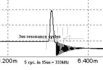
From MikeML's article, I zoomed in on the fastest ignition spark repetition rate and rise time and measured pixel width in an editor
3us (+/-20%) or 333 kHz resonance with fairly hjgh Q after detonation.
The cap across the switch does reduce radio interference.
As crutschow explain before the cap is important part of the circuit, without the cap there will be no current through the primary when the switch is open and there will be no spark.
I recognize the older bigger coils resonated at lower frequencies after the detonation with leaded high octane fuel burning longer.
Usually detonation is low impedance, 1 pulse , low Q ( no ringing)
and after detonation and arc extinguished, open circuit, high Q ringing.
Although I do not know the difference in detonation time for low and high octane fuel, I suspect it is in microsecond where slow burn is better for high compression with less blowby.
Of course the Cap reduces the slew rate before detonation and by resonant LC freq after. So but harmonic noise may be more problematic with DIY electronic ignition circuits.
Sign216 asks about whether substituting a transistor switch will improve the spark.
In general, the spark characteristics is generated by the coil characteristics.
It is well known that the ability to fire a spark plug plug improves with a reduced rise time of the spark voltage.
If you change the points from mechanical to electronic, but leave the coil as is, you will not see a significant improvement. In the attachment, in picture 6, is shown a typical 'Kettering' type of ignition coil. These types had a natural resonant frequency of around 1500 Hz and are quite slow. The development of high speed multi cylinder engines required better coil arrangements and this lead to coils with lower primary inductance and to limit the current at low speeds, a series, or ballast resistor was used.
I recently tested some Kettering coils and found the rise time was around 180 microseconds for a slow coil, around 150 microseconds for a faster coil, and around 120 microseconds for a fast coil. Each of these coils were used on 8 cylinder Chevrolet engines in a speed boat.
By contrast, when the change to electronic ignition and fuel injection took hold, the first change was to completely redesign the coil. The significant change was to change the magnetic circuit from the open long solenoid type used in the Kettering, to a closed magnetic circuit type used in modern engines. The closed magnetic circuit type significantly reduces the rise time. In the 1960's we built some close coupled ignition coils which had resonant frequencies of around 10 Khz, and these had rise times of 30 microseconds. If you look at an old type of ignition coil and compare it with one in amodern car, you will easily see the change in the physical proportions of the coil.
I havent checked any of the new coils, but generally as the rise time is reduced, the back EMF generated when the coil primary current is cut off is around 70 to 80 volt. The Mitsubishi car I drive has an electronic switch built into the distributor and when triggered, the electronic switch generates a constant width pulse to drive the coil.
There is a fair bit of optimisation that goes on with the ignition design, but generally the ADD ON types use more primary energy to generate a bigger, hotter spark which can cause spark plug deterioration at lower engine speeds. Typically, they do NOTHING to reduce the rise time of the spark voltage.
The modern designs use circuit arrangements and components which will give a uniform spark across the whole speed range of the engine.
In summary, if you change the points for a transistor switch, it is unlikely that you will see any performance improvement.
Hope this helps.
Rumpfy, thank you for the information. Let me ask, if the transistor switches faster than the points, won't that give a better spark?
I.e. a faster rise time. Esp. when starting, and the points are opening slowly?
Of course many argue that the points switch just as fast as the transistor. And I understand that a better/modern coil will improve things overall.
A transistor switch will basically eliminate the arc and pitting when the points open, but you still have the wear of the cam follower when you keep the points in place.
I have tested high voltage power transformers from 10kV to 150kV ( 5000 kVA type) with DC, 60Hz AC and standard rise and tail applied impulses ( similar rise time to a fast electronic spark plug ignition).
My conclusion was that at 2.5 us rise time ( controlled by large caps and power resistors) an arc discharge waveform will resist breakdown about 200% higher than a low frequency 60 Hz HV line.
This is due to the delay of energizing electrons to escape orbit and cause detonation or an arc.
DC can be much lower ( e.g. <30% of AC BDV) than AC if there is any dust or contaminants on the surface (creepage effect) and have "partial discharges or PD" , but if perfectly clean will be about the same DC=AC breakdown voltage BDV ... but that is irrelevant in this case... but thought I would add it anyways.
ESD can be as fast as 10 picoseconds from a charged finger.
Although my equipment could only measure 100 ps.
I was doing research on epidemic power distribution transformer failures in the field from H2 growth dissolved in oil in months instead of 25 yrs due to DGA tests caused by PD. I used a spark plug an automated ramping oil hipot tester to find the problem with the plug in a huge transformer tank of mineral oil.
more trivia... Low octane fuel in hot carbonized cylinder heads perhaps running too lean can pre-ignite aka "pre-ignition" before, during or just after TDC due to compression and temperature and fuel additives. High octane fuel is supposed to raise the excitation and release energy thresholds with additives.
CCK's bottom video shows the voltage due to points arcing.
However much power that subtracts from the spark energy would be saved by the transistor driver.
Whether that's a significant amount of energy or not is the question.
Edit: Okay, I did a rough calculation of the energy dissipated during the point arcing interval.
I used a typical 8mH coil operating at 5A current. The magnetic energy stored is thus 100mJ.
Enlarging the sparking area, it looks like it ramps to a maximum of about 3.5V in 1.5ms before the point current stops.
An LTspice simulation showed that during this time the coil current will drop from 5A to 4.73A.
The inductive coil energy at that current is about 89.5mJ.
The energy lost due to the point arcing is thus about 10.5mJ or 10.5% of the original coil energy.
Not sure how significant that is as far as spark effectiveness is concerned.
Very interesting. So the points booster would add 10%, on the arcing issue. Thank you for that learned calculation. I couldn't have gotten that anywhere.
Let me ask a related question. If there are three things slowing the voltage rise time (1-points opening, 2-transistor switching, 3-condensor), which is the slowest?
The points booster may help that issue, or it may end up slowing things down.
.....................
Let me ask a related question. If there are three things slowing the voltage rise time (1-points opening, 2-transistor switching, 3-condensor), which is the slowest?
.....................
Certainly the condenser is the slowest since it's purpose is to give the contacts time to open before the voltage builds up and the coil field starts to collapse.
The fastest would be the transistor (if the circuit is properly designed to rapidly turn off the transistor which I'm nor sure the Velleman circuit does).
For example, diode D3 prevents transistor T1 from rapidly pulling excess base charge from T2 to help speed it's turn-off.
A small capacitor across D3 would help
I don't see a good purpose for D3.
This site uses cookies to help personalise content, tailor your experience and to keep you logged in if you register.
By continuing to use this site, you are consenting to our use of cookies.