Continue to Site

Welcome to our site!

Electro Tech is an online community (with over 170,000 members) who enjoy talking about and building electronic circuits, projects and gadgets. To participate you need to register. Registration is free. Click here to register now.

  • Welcome to our site! Electro Tech is an online community (with over 170,000 members) who enjoy talking about and building electronic circuits, projects and gadgets. To participate you need to register. Registration is free. Click here to register now.

Alfa Romeo needs Vacuum Sensor Device

Status
Not open for further replies.

stevewaclo

Member
Hello,

Due to a complete lack of response elsewhere, I am posting this question and trust someone here at Electro Tech may may rise to the challenge.


Hello all,

I have travelled here many miles across the circuits of the interweb from the Alfa Romeo BB, optimistic the accumulated wisdom of Automotive Electrical & Sensor Forum (or Electro Tech) members will assist me in my quest.

Series 3 Alfa Spiders, from the early to late 80's used two different Bosch computers for their 2L, DOHV, L-Jetronic injected engines. One computer handles fuel, injection duties and the second, ignition timing. The latter computer has the following inputs: TPS (1/0), flywheel position sensor, flywheel RPM sensor (2 sensors on the flywheel?, don't ask and finally, the reason I'm here, a Vacuum Sensor Device (VSD).

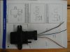
The VSD receives a vacuum signal from the intake manifold, and by means of a copper bellows (hey, I'm talkin' the 80's here ) moves a core within a coil to feed variable inductance to an oscillator in the Ignition Timing Computer. The computer massages the inputs and sends an appropriately timed (no pun intended) voltage to the ignition coil. Subsequently, the distributor functions simply as a four way, high voltage switch and does not factor into ignition timing in any way.

You're way ahead of me if you identified the weak link in this system to be the copper bellows, and tragically, all over this end of the galaxy, Alfa Spiders with failed VSD's have reverted to their base timing of 10degrees BDC, never again to provide improved fuel economy and performance .

A number of us on the Alfa Forum have considered, without success, a replacement A/D/A circuit for the VSD to no avail and are optimistic engineers here may have some ideas.

Here are the electrical specifications we have measured, using my VSD: Coil inductance at Max Vacuum (about 20#, limit of core travel), 3.6 mH; at zero vacuum (WOT) 2.5 mH. Resistance of the coil is 50 ohms. As an aside, have also discovered removing the electrical connection between the VSD and Ignition Computer results in ignition timing at idle going, to use the technical term, "nuts", with the timing mark jumping all over the harmonic balancer and manifold vacuum a shaky 5#.

On behalf of the hundreds of unhappy Alfa owners, I beseech you all to give our problem some thought and rise to the challenge!

Thanks and best wishes.

Steve Waclo, EE, ret (knew T. Edison personally)

Note: I presume the response of the coil is linear between limits.
 
Are you sure that you are calling the sensor by the correct name? Could it possibly be a MAP sensor? MAP stands for Manifold Absolute Pressure. There are many MAP sensors that do the same thing abut instead of a bellows they use a diaphragm. Here is a link to newer Alfa MAP sensors -
https://www.autosensors.co.uk/en/14-alfa-romeo

And one for checking the voltage values and some part numbers to compare with your part number -
https://www.electro-tech-online.com/custompdfs/2013/02/pg_si_0102_en_web.pdf

Hope this helps.
 
No, it's a VSD

shortbus,

Thanks for your reply.

The VSD I have referred to is indeed a vacuum sensor and, as described, sends a variable inductance value to an oscillator in the Bosch Ignition Computer (BIC).

During our ruminations, the crack Alfa BB Research and Development Committee had indeed considered using an easily sourced MAP sensor for our application, but would have ended up with an analog voltage which, only through the most torturous of manipulations, could have provided the variable inductance needed to supply the BIC.

So, if we are to keep our extant IC, we need to provide a variable inductance, over the range I detailed above, to the IC. Also considered was modifying an existing VSD. with a mechanism that could replace the broken bellows to adjust the coil core. In addition to being a packaging challenge, we would be back to a mechanical linkage of some sort (stepper motor?) and perhaps would not obtain the needed (reasonably) rapid response.

I'm on iPad and concerned about losing my work (where does the yellow highlighted "auto-save" save to?), will post a photo of a disassembled VSD shortly.

Best wishes.
 
If you can get into the ECU, maybe adapt this Variable freq MAP sensor to feed the ECU. This is a Ford part but i think they are made by Bosch. The freq is 75Hz to 150Hz.
 

Attachments

  • MAP SENSOR.JPG
    MAP SENSOR.JPG
    2.8 MB · Views: 1,662
Thanks for making a photo!

Debe,

Thanks for your response.

At the risk of sounding negative, I'm afraid opening up the IC would take me way out of my comfort zone. Perhaps with proper equipment, and you at my side, we could go in and identify the IC oscillator I referred to and use a 'scope to determine it's output to the next stage of the ignition control circuitry. If by chance that output happened to be the same voltage (easy to adjust) and frequency (more of a challenge) as the output of the MAF sensor you sent a picture of, we could eliminate the VSD and oscillator it feeds and operate the remainder of the IC circuitry directly with output from the MAF.

I was optimistic something could be done external to the IC, maybe using your MAF sensor or something similar, and additional circuitry to generate the variable inductance without the need to go inside the IC.

BTW, here's what used IC's are going for:

**broken link removed**

Used VSD's are available for around $90 (shipped) but the supply is inadequate to meet demand and i suspect there are many Spiders running at base timing (10 degrees) that would be operating much more efficiently with ignition advance up tom30 degrees.

One other thought. My Alfa BB homies and I have presumed the coil in the VSD is feeding an oscillator in the IC. I believe someone confirmed that during our discussions, but I'm not 100% certain.

Best wishes.
 
Additional 411 from another Forum

Hello everyone,

Here's a safe link to the Arduino Forum, where I have also sought guidance:

**broken link removed**

Excellent questions and food for thought abide there.

Thanks!
 
Hello KISS, may I call you KISS?


Once again I am faced with a well-meaning individual who encourages me to learn how to fish :).

At first, I thought the device you were referring to was akin to this:

https://m.youtube.com/#/watch?v=Ac7G7xOG2Ag&desktop_uri=/watch?v=Ac7G7xOG2Ag

I gotta get out of the house more!

Clearly there is much yet to be learned about the inner workings of the Ignition Computer and that will be my next task.

Film at 11.

Thanks again.
 
Hey, you never stop learning and since you are an EE, why stop now. You kinda asked for a voltage controlled inductor and the "pay source" suggested that circuits exist.

I knew of the gyrator so I worked forwards from there.

You should also try to ascertain the frequencies involved or even the waveform seen at the sensor.

You might very well end up with a processor based solution that uses some other sensor and uses a look-up table for the output.

You all need to learn if your operating in the Hz, kHz, or MHz region.

So, yea you have some work to do.
Frequency
Waveform
Inductance vs vacuum
Substitution of a real inductor
Substitution of a gyrator.
Synthesis of a voltage controlled gyrator
Use of a microprocessor (check out www.picaxe.com)
Prototype
Think about failsafe: e.g. no oscillation, disconnect device
Think about protection; Overvoltage etc.
Harden for automobile environment. (Some LT technology parts come to mind)
Go

Frequency vs Vacuum
 
Last edited:
I'm on it!

Hello KISS,

In earlier posts, I failed to mention that although I am a graduate of Penn State and earned the EE part, I left electronics shortly after the demise of vacuum tubes (a bitter dust-up with a gentleman named Shockley. You may have heard of him). So, technically I'm an EE who has retired, but from something else all together. Busted :(.

Touché on the never stop learning part.

Much appreciated is your list of items that require resolution as the project proceeds!

In a effort to learn more about internal workings of the Ignition Electronic Control Unit (IECU) [BTW, proper terminology makes Google so much more helpful] I have sent this email off to Bosch Engineering. A productive response would go a long way toward resolving many items on your list. No response last time, when I inquired about the Vacuum Sensor Device but perhaps this inquiry will garner attention:

Ooops. Copy/paste of that email was unsuccessful but suffice to say, I referenced this Bosch part number:

**broken link removed**

Let's see if they respond. Otherwise, I don't know where to proceed. Reverse engineering?

BTW, auto-save on this site is AWESOME. A simple mis-touch of iPad can be catastrophic :(.

Best wishes and I'll report back with any 411 from Bosch.
 
And because I like throwing out every idea, here is another one:

Suppose you create a variable inductor using a slug and an inductor. Again who knows how much dieplacement is required. For small diaplacements, an LVDT transducer could be used. See http://www.rdpe.com/displacement/lvdt/lvdt-principles.htm

http://www.macrosensors.com/GSA_750.html

Not cheap, though: http://uk.farnell.com/lvdt www.newark.com is down.

Or try to go open or closed loop with a voice coil actuator: e.g. http://www.h2wtech.com/Pages/Product-Detail.aspx?prodid=2

You get it all together a voice coil actuator and an LVDT transducer http://www.h2wtech.com/Pages/Voice-Coil-Positioning-Stages.aspx and you have what you need.

Then the question becomes, how to make it low cost.

In any event, you could try making one from a speaker.

Take the actuator that you have, spring load it and replace the vacuum side with a LVDT/voice coil actuator and go. it would not be cheap.

**broken link removed**

https://www.electro-tech-online.com/custompdfs/2013/02/15-BasicsOfVCMs-1.pdf

**broken link removed**

Maybe a low-cost way is to use and RC Servo http://www.pololu.com/catalog/product/1040 . But you do have to convert rotary to linear motion. See http://www.pololu.com/catalog/product/1350/resources for a controller?
 
Last edited:
I am delighted and astounded...

....by your wealth of knowledge and commitment to my project!

Thanks KISS.

This line from one of your links :

"One type of positional sensor that does not suffer from mechanical wear problems is the "Linear Variable Differential Transformer" or LVDT for short."

The part about inconsequential mechanical wear of the inductor is on target...the copper bellows, not so much. That being said, I suspect engineers at Bosch anticipated that something else in the Alfa would fail catastrophically long before the bellows system their ME's designed :).

Will make time to more thoroughly review (see earlier comment on continual learning) the links you sent and patiently await feedback from my email to Bosch. Clearly, a thorough understanding of the inner workings of the IECU will be invaluable when considering internal mods. A circuit, added within the protected case of the IECU and and powered by the no doubt stabilized and reliable power source there, would have a much better prospect for survival than an external add on.

Or am I making this harder than it needs to be? We know the electrical characteristics of the VSD (inductance over the operating range and a fixed resistance). A silicon bellows from Ford's VV carb of days gone by, as suggested by another contributor, reliably mated to the existing hardware, may work. Still torn between mechanical or electronic solutions and as you have pointed out, what functions on a bench may struggle in an automotive environment. An electronic plug and play solution while very attractive, will face serious reliability issues.

Arghhh. Too many variables head is going to explode :D.

Going to review pictures of the disassembled VDC, research the Ford VVC hardware and review your links. One good thing, my VSD is on it's way back from the engineer who made the electrical readings and if nothing else, I can reinstall it and my IECU will stabilize at 10 degrees of advance, restoring a smooth idle and putting me in the same situation as hundreds of other Alfa owners.

Beginning to anticipate the upcoming Autocross season with Reno SCCA!

Thanks again.
 
Do you have a graph of inductance vs vacuum? The inductance I can do, but I don;t have one of those vacuum thingys, but again it would be wise to know about what frequency the gizmo operates at in order to measure L.

I suppose a collection of
Vacuum, displacement, frequency and inductance and possibly timing and current would help.

BTW, What is the maximum displacement of the sensor?

Yea, the LVDT sensor was the first that came to mind based on an Angstrometer we has at work. It measured the thicknesses of sputtered and e-beamed films to a very high accuracy.

I might just have to be sloppy to work. At least it's relatively safe.

Again, I want to thow out something that may or may not be useful. Speaker re-coning kits: https://www.simplyspeakers.com/cerwin-vega-speaker-recone-kit-152w-rk-cv152w.html Just somewhat suggesting using a voice coil repair kit and your own form of sort to make a simple transducer. Some speakers are ferofluid cooled. Again food for thought.

In any event, I'm thinking of an RC Servo and one of the pre-made controllers to acttivate what you currently have or say a powderd iron slug for a medium cost, moderate relaibility.

A voice coil transducer, either open or closed loop. Open loop may be all you need.

A perfect and expensive marriage might be a LVDT, voice coil transducer and a powdered metal core inductor.

And again, for something wierd, is a Roller inductor, **broken link removed** These are used to auto-tune RF transmitters.

Check patents at patents.google.com e.g. 6114938

How about this for wierdness, electrically switching various inductors in parallel combinations. Maybe discrete values in parallel would work. Kind of like 8 binary inductances would give you 255 values. Use OPTO MOS switches to switch them into place. These are LED based solid state switches. Just one example: https://www.electro-tech-online.com/custompdfs/2013/02/CPC1017N-1.pdf

It might be a little more complicated if you want to keep the series resistance in line. The OPTOMOS relays are available in other configurations.

I wonder if that's worth pursuing?
 
Last edited:
KISS,

Answers to most of your questions are within this now 5-page post, but unless you have a lot of time I don't expect you to plow through it:

https://www.alfabb.com/bb/forums/spider-1966-up/201079-calling-all-ees-challenge.html

A few salient points:

Estimated inductance values from Post 42:

For a range of 2.55 to 3.8, using commonly available values of 0.22, 0.33, 0.39 and 0.68 with an additional unswitched 2.2mH inductor would cover a range from 2.2 to 3.82.
Even without "smart" binary switching, those 4 values still give a more-or-less linear progression - although the last step is a little larger than the rest. (But is it a linear curve that's needed here?)

As noted, R=50 Ohms

Oscillator frequency, unknown

Limit of core travel has been approximated by someone who opened one up. Still searching.

For vacuum/degrees of advance info, see post 13 here:

https://www.alfabb.com/bb/forums/spider-1966-up/35224-reposting-missing-pictures.html

Regarding speaker coil options, I'm attempting to source a diaphram actuator from a Ford, Variable Venturi Carb, and leap frog too much DIY assembly.

See part on right side of second drawing here:

**broken link removed**...

Later
 
You know, with a computer controlled engine, the exact value of vaccum may be unimportant, just as long as it varies with engine load and is within a designated range. In reality, vacuum senses the engine load, but the actual number may be of less importance. See: http://dnr.louisiana.gov/assets/TAD/education/ECEP/auto/h/h.htm

Interestly, I took a look at some inductors around the values you suggested at Digikey, and they do have in internal R of around 50 ohms.

Take a serious look at using binary weighted inductors. 8 would give you 255 steps, 7=127, 6=64. Maybe 127 steps is enough.

I doubt it would matter, much, but series resistances could be added into the circuit as well. See http://en.wikipedia.org/wiki/RLC_circuit for some ideas as to how R might affect the circuit. So 7 50 ohm inductors in series would end up to be 70 ohms of R. Nonetheless, some amount of compensation could be done in software.

I think you going to have to find a way to measure the frequency, and to compare say a 50 ohm fixed inductor with one that is made with the parallel combination of two that give the same value. ie. Figure out what the effect of a series resistance of R is, keeping it from say 25 to 50 ohms.

The OPTOMOS thing is looking more promising.

How about 7 inductors that could be in parallel and 7 or so series resistors. So, you just select the inductance and the series resistor dependiing on how many bits are on. The OPTOMOS relay will also add some resistance. Just selct one with a low on resistance which, of course, means more expensive.
 
Last edited:
Steve:

Your last link is dead. Did the idea of switching inductors come up before? Four may not be enough.

Noted: Do you have to maintain a close series resistance?

Time to get a cheap scope. e.g. **broken link removed**
 
Have occasionally needed a 'scope!

KISS,

"Time to get a cheap scope. e.g. http://www.ebay.com/itm/New-Mini-Nan...item2a27093299"

At first I thought it was an IPad accessory with an app, but it's stand alone! How do the Chinese manage?

And my birthday is right around the corner (2/8) !!

This link to the VV Carb should work. Second drawing, right side:

https://www.geocities.ws/julianvz/Sierra/Carbs/ford_vv.html

Multiple switched inductors have been considered and I believe we were going to put them in series. As you observed, maintaining R=50 will be another challenge (see below).

Check out Post 45 here for electronic suggestions from one of our members:

https://www.alfabb.com/bb/forums/spider-1966-up/200971-manifold-pressure-sensor-3.html

Regarding how many inductors, while the extant VSD provides essentially infinite inductance, and hence infinite ignition advance values (within IECU output limits), I don't believe we need to put too fine a point on our device. Considering real world operation, 10 degrees at idle (2.5 mH), WOT 30 degrees (3.8 mH) and perhaps two intermediate values for cruise...of course I'm presuming all flat roads :). More would be better, but there we go with complexity.

BTW, nada from Bosch on the internals of the IECU so unless someone can do some serious circuit analysis in that device, we're limited to external solutions. Believe I will pick up the phone tomorrow.

On the subject of oscillators, found this in the link you sent:

Oscillators

For applications in oscillator circuits, it is generally desirable to make the attenuation (or equivalently, the damping factor) as small as possible. In practice, this objective requires making the circuit's resistance R as small as physically possible for a series circuit, or alternatively increasing R to as much as possible for a parallel circuit. In either case, the RLC circuit becomes a good approximation to an ideal LC circuit. However, for very low attenuation circuits (high Q-factor) circuits, issues such as dielectric losses of coils and capacitors can become important.

May we presume 50 ohms met the "as low as possible criteria" ? Suppose if that's what the coil winding turned out to measure, they worked with 50 ohms and the required capacitor is internal to the IECU. As you said earlier. R would need to be held close to 50 for all combinations of switched coils.

Thanks again for making time in what I'm sure is a hectic schedule.

Take a break and I'll get continue my search for the VV Carb piece and try to contact someone from Bosch.

Best wishes
 
Status
Not open for further replies.

Latest threads

New Articles From Microcontroller Tips

Back
Top