Continue to Site

Welcome to our site!

Electro Tech is an online community (with over 170,000 members) who enjoy talking about and building electronic circuits, projects and gadgets. To participate you need to register. Registration is free. Click here to register now.

  • Welcome to our site! Electro Tech is an online community (with over 170,000 members) who enjoy talking about and building electronic circuits, projects and gadgets. To participate you need to register. Registration is free. Click here to register now.

7 Transistors Triangle Wave Generator (Highly Linear)

Status
Not open for further replies.

iimagine

New Member
Google Triangle Wave Generator almost all that you get are circuits that employ 2 comparator/opamp ect...
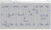
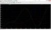
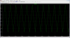
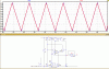
Well I wanted an alternative, more efficient way of doing this! So I designed this circuit in LTSpice. It simulates well, giving a very nice, highly linear waveform. uses very little power! The only problem is that I dont have a lab (I only have a breadboard and a DMM). I'm asking for help on test this out. Any comment or suggestion is much appreciated.

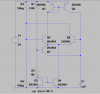
Use 2N2369 or faster transistors for Q5/Q6/Q7 for higher frequency (timing cap value less then 1nF as crutschow (a member in another forum) suggested.)

PS: This is not the first forum that I have posted this in, but since no one seems to be interested in testing this out, I'm asking for help here, hopefully someone will find this interesting and useful enough to bother with it.

Thanks in advance.
 

Attachments

  • DTO_12khz.PNG
    DTO_12khz.PNG
    34.7 KB · Views: 1,470
  • DTO_1nF_Ouput.PNG
    DTO_1nF_Ouput.PNG
    88 KB · Views: 913
  • DTO.asc
    1.9 KB · Views: 345
hi,
Where on the LTS asc circuit are you taking the triangle output from.?
E
 
Look at the current into C1. Because it is not constant the triangle has some distortion. (non linear)

Where you take out the triangle wave is critical. If the next stage loads C1 down there will be more distortion.

The circuit is clever. I would not have thought of it. I normally use a op-amp with high gain to hold the current more constant.
 
hi,
I did notice that the rise and fall times of the sawtooth are not identical, its an interesting circuit.
Have you tried a LTS sim with a fast OPA connected to the Cap output.?
E
 
Ye
Look at the current into C1. Because it is not constant the triangle has some distortion. (non linear)

Where you take out the triangle wave is critical. If the next stage loads C1 down there will be more distortion.

The circuit is clever. I would not have thought of it. I normally use a op-amp with high gain to hold the current more constant.
Yes it is not linear, my bad
 
hi,
I OPA from the LTS library, LT1215 gives a reasonable buffer operation for the Cap.
E
 

Attachments

  • AAesp01.gif
    AAesp01.gif
    35.1 KB · Views: 800
If true linear is desired then substitute r3/r4 with a current source. However, the output will then swing from 0-5v approx.
A simple emitter follower can be use to buffer the output
 
Hmm...still no one want to test this out.
How about this: If proven to work, and by using UHF transistors, this little circuit can generates signal up to Mhz range
Cheap + Efficient for the hobbyist!
Think GREEN :)
 
Hmm...still no one want to test this out.
How about this: If proven to work, and by using UHF transistors, this little circuit can generates signal up to Mhz range
Cheap + Efficient for the hobbyist!
Think GREEN :)
hi iim,
Its not that we would not want to test it out.:)
As it requires at least a high speed buffer OPA, it is more practical to buy a dual or quad high specification OPA and construct a 'regular' triangle generator.

E
 
hi iim,
Its not that we would not want to test it out.:)
As it requires at least a high speed buffer OPA, it is more practical to buy a dual or quad high specification OPA and construct a 'regular' triangle generator.

E
It is not true that a high speed OPA is required. Like I said a simple emitter follower can buffer this. Check out this Discreet Class D amp that I design for it

Note: The Fets are still undecided, these are just conveniently available from LTSpice library so I use them to simulate
 

Attachments

  • Discrete Class D Amp For Fun.asc
    4.6 KB · Views: 268
  • CDA_v1.3.PNG
    CDA_v1.3.PNG
    90.9 KB · Views: 636
  • CDA_v1.3_Output.PNG
    CDA_v1.3_Output.PNG
    94.5 KB · Views: 409
Last edited:
Hello there,

Well, depending on accuracy and range you can do a triangle wave generator with something like three transistors. Two transistors form a multivibrator, then the third is a constant current generator that charges a cap. The constant current means the cap voltage ramps up linearly.

You could also check some older TV schematics (non tube type) and maybe some oscilloscope schematics for more ideas too. If it's a tube type you'd have to convert the circuit to transistor yourself.
I would love to see this 3 transistors triangle generator that you speak of.
 
Hello again,

Well do you know what a two transistor multivibrator circuit looks like? That's just a circuit that outputs a square wave (or more like a pulse depending on component values). The output of that would drive a constant current transistor circuit that charges a cap. Of course we might want to discharge quickly so maybe a fourth transistor to discharge the cap faster. In this case the fourth transistor would be driven with the multivibrator while the constant current transistor just kept on passing a constant current.

For the simplest constant current generator we would use say two diodes and a resistor with that one transistor.

We could also probably find a simplification.

If you still cant visualize this i'll try to draw up a schematic.
 
Hello again,

Of course we might want to discharge quickly so maybe a fourth transistor to discharge the cap faster.
For the simplest constant current generator we would use say two diodes and a resistor with that one transistor.

We could also probably find a simplification.

If you still cant visualize this i'll try to draw up a schematic.

What you are saying will create a sawtooth waveform, not a triangle one

I know what a multivibrator circuit look like, what I wanted was the detail of how you use that to generate a triangle wave . It also defeats the purpose of GREEN (saving energy)
 
hi iim,
I hope you dont think I am trying to put your designs down, but you must realise if you post a circuit diagram you must expect your peers to ask questions.o_O

Most hobbyist circuits need to have an application use, your original circuit only shows the generation of a triangle waveform, which is not highly linear nor is a it a true 1:1 sawtooth.
As a stand alone circuit its a very interesting concept, but it requires additional circuitry to make it a practical project for an hobbyist.
ie: Frequency control, amplitude control and offset shift control
This is the point I raised earlier, a workable generator with the required controls and buffering could be achieved with a high spec quad OPA..

Your for fun Class D amp shows a very good sine wave at the output in simulation , using your saw tooth gen.
Eric
 
What you are saying will create a sawtooth waveform, not a triangle one

I know what a multivibrator circuit look like, what I wanted was the detail of how you use that to generate a triangle wave . It also defeats the purpose of GREEN (saving energy)

Hello there,

Well, the word "triangle" is a generic term which means, well, just that, a triangle. And triangles come in many forms because it's just an object with three sides, not necessarily equal.

But you are right in that what i was talking about could be called a sawtooth generator, and i wasnt sure if you cared about having an equilateral triangle or a sawtooth until now.

So if that does not interest you then sorry about that, but maybe we can still work out a simpler circuit anyway.
The difference between the sawtooth ramp mechanism and the triangle with two equal sides is how the cap charges and discharges. Since with the sawtooth we assume a very fast discharge through a low impedance, what we would have to do to get a more balanced triangle is we would have to add another constant current generator that would discharge the capacitor. That would use the same transistor as the sawtooth only a bit more complicated with a few more components like two more diodes. We'd then try to use the multivibrator output to drive this second constant current stage. If the current was set to 2 times the first constant current value we should see a triangle with equal sides.

Sound interesting or no?

I was just throwing out some ideas so you can think about them and decide what you like best. It's always up to you what circuit to use as you are the one that will be using it :)

I've included a block diagram.
 

Attachments

  • TriangleGenerator-2.gif
    TriangleGenerator-2.gif
    13.1 KB · Views: 411
Last edited:
Thank you ericgibbs and all who have respond to this po
Hello there,

I've included a block diagram.

Hi,

I have already considered this before and have come up with a way of doing it. Its a true 1:1 triangle, perfect linear but requires too many components so I abandoned it.
Because a perfect linear 1:1 triangle is not what I am looking for, therefore I like this 7 transistors circuit better
Thanks for your suggestion though :)
 

Attachments

  • Square_Triangle.PNG
    Square_Triangle.PNG
    56 KB · Views: 472
hi iim,
Have you approached a local university to see if their electronic lab would use it as a student project.?
E
 
Status
Not open for further replies.

Latest threads

New Articles From Microcontroller Tips

Back
Top