Raiway Pete
New Member
Seems like a lot of components compared to my 8, 4 diodes, 2 transistors, 1 resistor and 1 optocoupler.
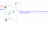
Now I need to work out the connection of the optocoupler instead of the led and then the pcb for a detector only circuit with 2 connections one side (dcc power) and 3 the other (12V, Gnd, Detect)
Ok angie,
Do yourself a favor here. Leave your PC board as is. This is a prototype and you should leave a little wiggle room for enhancement and changes. Once an engine runs for half an hour and the LED stays on then add the Opto-isolator. (Try leavingthe LED in the circuit. It makes a good visual indicator of the "detect" condition.) One question. Where are you going to locate the opto isolator. On the detector board or the signal controller board?
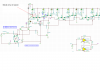
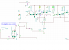
I added the diodes to the circuit, changed PNP to NPN and inserted signal transistors instead of power ones.
P
P.
")