Continue to Site

Welcome to our site!

Electro Tech is an online community (with over 170,000 members) who enjoy talking about and building electronic circuits, projects and gadgets. To participate you need to register. Registration is free. Click here to register now.

  • Welcome to our site! Electro Tech is an online community (with over 170,000 members) who enjoy talking about and building electronic circuits, projects and gadgets. To participate you need to register. Registration is free. Click here to register now.

Waterfall Printer simulator

Status
Not open for further replies.

Mosaic

Well-Known Member
Hi All:

The thread on waterfall simulators:

https://www.electro-tech-online.com/threads/waterfall-printer.114242/

Has piqued my interest.

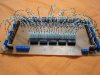
But, I think i need a tool to help simulate it before investing in a bunch of solenoid valves etc.

So here's the deal:

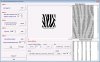
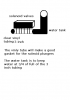
I want to send serial data asterisks to windows 'Terminal' including carriage returns so that I can 'Paint" the screen with the simulated water streams.

So if I want to simulate a 96 valve system I will have 96 characters per line and then a Newline (no CR) and then a line of asterisks and then a CR. Thus pushing the lines down the screen one by one....not adding new lines to the screen. I need to PUSH existing lines down the screen with new data coming on top.

How can this be achieved from a PIC and a USB conn? Serial over USB? Any links to do that?
 
Last edited:
This one mike?

**broken link removed**

I am not clear on how to comm with it from the PIC side...do u have any asm code samples i can study?
 
That vendor didn't include the CD. Consider ordering from the vendor I posted later in that thread.

Use the PIC USART module just like you would with a serial RS-232 connection.
 
Last edited:
I'm sorry. I didn't realize you haven't done UART code yet.

There are hundreds of examples around but if you don't feel like searching then here's one you can use with Hyperterminal to play with and study;

Code:
;******************************************************************
;*                                                                *
;*  Filename: 16F88 USART Test.asm                                *
;*    Author: Mike McLaren, K8LH                                  *
;*   (C)2010: Micro Application Consultants                       *
;*      Date: 19-Aug-06                                           *
;*                                                                *
;*   16F88 USART Test Program                                     *
;*                                                                *
;*                                                                *
;*     MPLab: 7.40    (tabs=8)                                    *
;*     MPAsm: 5.03                                                *
;*                                                                *
;******************************************************************

        processor PIC16F88
        include   P16F88.INC
        errorlevel -302
        list st=off

        __CONFIG  _CONFIG1, _LVP_OFF&_PWRTE_ON&_WDT_OFF&_INTRC_IO
        __CONFIG  _CONFIG2, _IESO_OFF&_FCMEN_OFF
;
;       _CP_OFF                 ; default, no code protect
;       _CCP1_RB0               ; default, CCP1 on RB0 pin
;       _DEBUG_OFF              ; default, debug mode off
;       _WRT_PROTECT_OFF        ; default, write protect off
;       _CPD_OFF                ; default
;       _LVP_OFF                ; -- low voltage programming off
;       _BODEN_ON               ; default, brown out detect on
;       _MCLR_ON                ; default,
;       _PWRTE_ON               ; -- power up timer enabled
;       _WDT_OFF                ; -- watch dog timer off
;       _INTRC_IO or _HS_OSC    ; -- INTOSC
;

PtrL    equ     h'20'           ; PutString routine
PtrH    equ     h'21'           ; PutString routine

;
;  PutStr macro - print in-line character string
;
PutStr  macro   str             ;
        local   String, Print
        movlw   low String      ;
        movwf   PtrL            ;
        movlw   high String     ;
        movwf   PtrH            ;
        goto    Print           ;
String  dt      str,0
Print   call    PutString       ; print string
        endm

;******************************************************************
;*                                                                *
;******************************************************************
        org     0x000
v_reset
        clrf    STATUS          ; force bank 0, IRP 0             |B0
        clrf    PORTA           ; clear PORT A latches            |B0
        clrf    PORTB           ; clear PORT B latches            |B0
        bsf     STATUS,RP0      ; bank 1                          |B1
        clrf    ANSEL           ; setup PORT A digital I/O        |B1
        clrf    TRISA           ; setup PORT A all outputs        |B1
        movlw   b'00100100'     ;                                 |B1
        movwf   TRISB           ; set RB5/TX & RB2/RX as inputs   |B1

        movlw   b'01110000'     ;                                 |B1
        movwf   OSCCON          ; select 8-MHz INTOSC clock       |B1
Stable  btfss   OSCCON,IOFS     ; Int Osc Freq Stable bit set?    |B1
        goto    Stable          ; no, branch and wait             |B1

        movlw   d'25'           ; 25 (8-MHz) or 64 (20-MHz)       |B1
        movwf   SPBRG           ; 19200 baud                      |B1
        movlw   b'00100100'     ; TXEN=1, SYNC=0, BRGH=1, TX9=0   |B1
        movwf   TXSTA           ; Async, 8, 1, none               |B1
        bcf     STATUS,RP0      ; select Bank 0                   |B0
        movlw   b'10010000'     ; SPEN=1, TX9=0, CREN=1, ADDEN=0  |B0
        movwf   RCSTA           ; enable serial port              |B0
        movf    RCREG,W         ; flush Rx Buffer                 |B0
        movf    RCREG,W         ;                                 |B0

        PutStr  "\x1b[2J"       ; home cursor, clear screen       |B0
        PutStr  "K8LH 16F88 UART Test v1.0\r\n\n\n"

Loop    call    Get232          ;                                 |B0
        call    Put232          ;                                 |B0
        goto    Loop            ;                                 |B0

;******************************************************************
;
Get232  btfss   PIR1,RCIF       ; character available?            |B0
        goto    Get232          ; no, branch, else                |B0
        movf    RCREG,W         ; get character                   |B0
        return                  ;                                 |B0
;
Put232  btfss   PIR1,TXIF       ; transmit buffer empty?          |B0
        goto    Put232          ; no, branch, else                |B0
        movwf   TXREG           ; send character                  |B0
        return                  ;                                 |B0
;
PutString
        call    GetTable        ; get a table character           |B0
        andlw   b'11111111'     ;                                 |B0
        skpnz                   ; 00 byte, last character?        |B0
        return                  ; yes, return                     |B0
        pagesel Put232          ;                                 |B0
        call    Put232          ; else,output character           |B0
        incf    PtrL,F          ; increment pointer               |B0
        skpnz                   ;                                 |B0
        incf    PtrH,F          ;                                 |B0
        pagesel PutString       ;                                 |B0
        goto    PutString       ;                                 |B0
GetTable
        movf    PtrH,W          ;                                 |B0
        movwf   PCLATH          ;                                 |B0
        movf    PtrL,W          ;                                 |B0
        movwf   PCL             ;                                 |B0

        end
 
Last edited:
Mosaic I think I have the water printer nozzle worked out. I figured out one that I know would work and be easy to make.
 
What's the concept?

I did a bit of initial design around 12vdc spring/solenoids, set up to plug intake tubing routed to the waterfall transom. So all tubes are plugged with no power, and open when solenoids are powered. The solenoid rail sits IN the water inside of a special pressure box in the main base recovery tank. Water is pumped into this pressure box. That way all the tubes get the same hydrostatic pressure and should flow the same.

That's what i planned to test 1st. After I get the simulator working.
 
This is my idea
 

Attachments

  • water printer.PNG
    water printer.PNG
    10 KB · Views: 423
Sounds similar to my concept. Therefore I agree....

What is the resolution of these 'printers', are we talking 1/4", 1/2" streams, 1" streams? How many streams are required for a 12 foot wide unit? What is the spacing of the streams? Is it like a 25% DC...1" streams spaced 1/4" apart or 1/4" stream spaced 1/16" apart?

These issues must be solved in order to know the # & size of solenoids required.

I envisage the controller taking a serial data set from a PC which describes the state of the solenoids, probably down to 16ms accuracy. 16ms is reasonable for a solenoid valve full stroke response.
At 10m/s^2 acceleration, after 1 second the avg velocity of the water is 5m/s, therefore the water has fallen 5 m in 1 sec. adding a water velocity (est.) of 2m/s based on pump pressure we have water falling 7m in a second. A decent size Waterfall might be about 3.5m high => 0.5 second water transit time. Or each graphic pattern visible for less than that. A 16ms actuator will then give a resolution of 7*.016= 11.2 cm or about 4.5 inches of water. So the minimum graphic size is 4.5" tall. This does not affect making smooth shapes except for the left & right edges of a circle.

At 16ms, we have about 63 data sets per second. These are 1 bit depth data sets for a flat waterfall. If we have 128 solenoids running, that's 63*128 = about 8Kbits per sec. Quite doable at a 9600 baud rate. At the full 9600 baud we can support 152 solenoids.

I expect to have the MCU interface with the PC via UART and feed a cascade of these devices:
TEXAS INSTRUMENTS|TPIC6A595NE|IC, 8BIT SIPO SHIFT REGISTER, | Newark.com

For 128 solenoid drives we need 128/8 = 16 of them, no FET drivers or flywheel diodes required.
To clock 128 bits into these shift registers at 8Mhz MCU clock rate we have a 4 uSec per clked bit (8 asm instructions) => 128 * 4 = a half millisecond latency, which is decent. Since the latency is consistent it won't affect the display appearance, just delay the onset of the display.
in fact, we can clk the bits into the shift registers AS they are received by the UART...no buffering, then latch them at the 128bit mark and repeat for the next 128 bits. Down to a uSec latency then.

Edit: As an added feature use 8 more bits to drive 8 Coloured Lights for light sequencing effects.


Please point out any flaws in this approach....or better yet, suggest a better one! i think a 16F can handle this job.
 
Last edited:
I been dreaming up a good idea I think I have it just waiting on the parts. Every year it gets slow at Xmas in the repair business. So I'm waiting for the cash LOL. But I have a good ideal how to make this

I'm going to winded 8 bobbins that set on top of a piece of pvc pipe that I drilled 8 holes in and used brass pipe to guide the the valve to block the holes in the bottom of the pipe.
Then just scan and print your water drops
 
Hi interesting project:)
I have almost completed the waterfall with 40 Solenoid valves ,the Simulator, electronics and a graphical software to generate the bytes from pictures and send to the microcontroller.
Will soon post the details.
Regards
 

Attachments

  • graphical waterfall software.jpg
    graphical waterfall software.jpg
    311.5 KB · Views: 800
  • controller2.jpg
    controller2.jpg
    63.5 KB · Views: 409
  • solen.jpg
    solen.jpg
    60.9 KB · Views: 360
  • pipe1.jpg
    pipe1.jpg
    47.2 KB · Views: 514
  • Sketch of Graphical fountains1.jpg
    Sketch of Graphical fountains1.jpg
    152.3 KB · Views: 514
That looks pretty good. Can you share the Gui software to xmit the gfx to the PIC with us? I guess it's a serial out?
 
The Software send the bytes to the Arduino through USB which then send 5-bytes(40 bits) to Qty:5Ea 74HC595 shift registers. I am using IRF540 to control the solenoids.

The Software is working perfect and at 9600 baud i am having no loss of data. Attached is the file that is generated by my software for various designs for 40 solenoid valves (5-bytes per row).the file can be open in any text editor i.e. Wordpad or MSword and Select the font TERMINAL and font size =8 for best view. i am fine tuning the software and will consider sharing it later.

Yesterday the installation of Header and solenoid was carried out. Now wiring the solenoid will take time, hope i will be able to test the complete system by the weekend.


To all electronics GURUS , How can we increase the Solenoid response time electronically? So that i can Quickly ON/OFF solenoids...
 

Attachments

  • installation of header.jpg
    installation of header.jpg
    29.6 KB · Views: 305
  • fountain designs.doc
    566 KB · Views: 436
What is the spec on the solenoids u have? As far as I have seen 20 to 40ms is the best u can hope for.
If u parallel solenoids and add another output routine to your code u can halve the response times. But at around $10 to 15 for a solenoid it get's pricey doubling up on those. Also adds more chance of a solenoid failure.
 
Last edited:
Status
Not open for further replies.

Latest threads

New Articles From Microcontroller Tips

Back
Top