Continue to Site

Welcome to our site!

Electro Tech is an online community (with over 170,000 members) who enjoy talking about and building electronic circuits, projects and gadgets. To participate you need to register. Registration is free. Click here to register now.

  • Welcome to our site! Electro Tech is an online community (with over 170,000 members) who enjoy talking about and building electronic circuits, projects and gadgets. To participate you need to register. Registration is free. Click here to register now.

Would this fan-controller work? Basic transistor math.

Status
Not open for further replies.

Lac

New Member
Hi there.

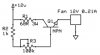
Im currently planning a simple and cheap fancontroller, to learn how to use transistors really. The fan used is rated at 12V 0.21A, I have figured out that the fan will stop rotaing when it is only feed 0.048.A, and the transistor im using have a hfe value of 400, that would mean that if i want 0.048A to pass through the transistor i need to have a current of 0.048A/400=0.00012A at the base. And to get that i need a resistor of 12V/0.00012A=100k connected to the base of the resistor. And to protect the pot from the hig current, I need to connect a resistor valued to 1k in front of the pot.

Lastly I would need to connect a resistor after the transistor to limit the current going through it to a value under the max value 0.5, the resistor need to have a wattage rating of at least 12V/68R=0.1764W.

So that would mean that when the pot is turned to 100k, it would only go 0.0476435...A to the fan. And when the pot is turned to zero, it would go 0.176470...A to the fan.

phew! lots of writing there :oops: , but does this generally looks right to you?

In advance, thanks.
 

Attachments

  • fancontroller.jpg
    fancontroller.jpg
    27.8 KB · Views: 960
  • datasheet.jpg
    datasheet.jpg
    33.4 KB · Views: 686
If your intention is to use a linear circuit just for the purpose of learning the circuitry, great! However, any linear circuit suffers from a problem with efficiency. Anything the fan isn't using is lossed across the pass transistor. A better solution is to use a 555 timer and vary its pulse width, feeding the output to a MOSFET or NPN in a common drain/emitter configuration. If you get the switching frequency down too low, you'll hear it in the fan winding, so keep it well-above 20KHz so that you keep cool while still warding off the mosquitos.

Dean
 
Simple 12v Fan Control

Lac
You have made a few mistakes on your maths - all your calculations seem to assume 12v across every component (which isn't true!)

If you use the configuration you have drawn (common collector - load in emitter leg), then the sums for me are as follows :-

Common Collector (as drawn):

Assuming fan is a constant resistance, 12v/0.21A = 57R
If the transistor is turned fully on then you have a 68R resistor in series with the fan.
57R/(57R+68R) = 45.6% of 12v = 5.5V available to the motor.
The series resistor is not required anyway, the motor will be the load for the transistor, it only takes 0.21A with 12V across it so there is no way you will see 0.5A through the transistor!

A silicon bipolar transistor will drop 0.7V between base and emitter when it is biassed on so to get the maximum power to the motor you need the base voltage to be as high as possible and the emitter will try to follow (with the 0.7V drop). If you connect the base directly to the 12V supply then the transistor's emitter will rise to 11.3V (this configuration is also called an emitter follower as the emitter simply follows the base voltage!).

If we stick with the assumption that the motor has a constant resistance of 57R and you say 0.048A is the minimum current you require then this equates to 57R*0.048A = 2.736V
To make the emitter control at this voltage we set the base at
2.736V+0.7V = 3.436V
So the base resistor needs to drop 12v-3.436V = 8.564V
With a current of 0.048A/400(hfe) = 120uA
So R3 (the base resistor) is 8.564v/120uA = 71367R or 71k4

This means R3 needs to vary from a dead-short to 71.4K
NOTE that this allows a maximum of 11.3V to the fan motor.

Alternatively, you could use a common emitter circuit (see drawing below), this would allow almost the full 12V to the motor but isn't quite as tolerant as the common collector circuit, being more sensitive to transistor temperature (thermal runaway?) and supply voltage changes.
Common Emitter:

Emitter current (Ie) =0.21A (for full speed, 12V)
:. Ib = 0.21/400(hfe) = 525uA
Vb = 0.7V (0.7V above the emitter, which is now always 0V)
Rb drops 12V-0.7V = 11.3V

Rb = 11.3V/525uA = 21524R (or 21k5, a bit extra won't hurt!)

Emitter current = 0.048A (fan stalled)
Still assuming the fan motor is a constant 57R.
Ib = 0.048A/400(hfe) = 0.00012A (or 120uA)

Rb = 11.3V/120uA = 94167R (94k)

So Rb wants to vary from 21k5 to 94k
I have made no attempt to rationalise the resistor values as both circuits will need to be corrected for the transistor's hfe, your data says it could be anywhere from 250 to 600. My calculations assume your quoted hfe of 400.

And you thought your posting had lots of writing :!: :wink:
 

Attachments

  • simple_transistor_fan_control.gif
    simple_transistor_fan_control.gif
    6.5 KB · Views: 852
Status
Not open for further replies.

Latest threads

Back
Top