Continue to Site

Welcome to our site!

Electro Tech is an online community (with over 170,000 members) who enjoy talking about and building electronic circuits, projects and gadgets. To participate you need to register. Registration is free. Click here to register now.

  • Welcome to our site! Electro Tech is an online community (with over 170,000 members) who enjoy talking about and building electronic circuits, projects and gadgets. To participate you need to register. Registration is free. Click here to register now.

Would this circuit work?

Status
Not open for further replies.

CoTang

Member
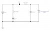
Hello again! My friend designed this cheap recharger circuit for NiMH for me and I was wondering about some of the components that are used in it. Hopefully the picture shows up. My question are; is D2 used for preventing the current from the Recharge battery to flow back to the main power source, and also I'm assuming that the cap is to filter out unwanted noise, now, how do you know what values to use for that? Also what would I need to prevent the battery from over charging? I was thinking of adding a "Sensing Resistor" and a transistor to sense when its about full and have the transistor turn the power off. Will that work? Thanks again!
 

Attachments

  • circuit_305.jpg
    circuit_305.jpg
    12.3 KB · Views: 946
CoTang said:
My question are; is D2 used for preventing the current from the Recharge battery to flow back to the main power source, and also I'm assuming that the cap is to filter out unwanted noise, now, how do you know what values to use for that?

Yes, it's to prevent the current flowing back, assuming the source battery is always charged it wouldn't be needed, but if it was flat (or disconnected) it prevents current flowing back through the LED, or into the flat battery. I don't see as the capacitor is needed at all, it wouldn't make any difference for a simple circuit like this.

Also what would I need to prevent the battery from over charging? I was thinking of adding a "Sensing Resistor" and a transistor to sense when its about full and have the transistor turn the power off. Will that work? Thanks again!


It's not as simple as that, charging a NiMh or NiCd follows a 'Delta V' curve, which means as it's fully charged the voltage strarts to drop slightly, you need to detect this slight voltage drop (which isn't simple!).

But in this case it's not required, the charging current is only set to be 5mA, only a trickle charge - so it can be left on charge permanently.
 
Nihm charging circuit

Hey thanks for the quick response. What if the the battery is rated at 1700mAh and I'm chraging it with 17mA can it be left on continous charging? I know I can use a maxim chip to accomplish this but I don't think I have the room on the board for it (with all the other stuff). Plus its good practice for designing.

P.S.
Hey how did you get 5mA? It weird, without the Battery, the current reading from the output of the cap is approx 17mA (Which is what I wanted to get, but when I put the battery in it becomes 5mA). Hmmm.... I think I might have to use ohms law with the 9.6V instead of the 14V. Am I Correct?

Thanks.
 
Re: Nihm charging circuit

CoTang said:
Hey thanks for the quick response. What if the the battery is rated at 1700mAh and I'm chraging it with 17mA can it be left on continous charging? I know I can use a maxim chip to accomplish this but I don't think I have the room on the board for it (with all the other stuff). Plus its good practice for designing.

17mA is only 1%, so you could happily leave it permanently on charge at that rating.

Hey how did you get 5mA? It weird, without the Battery, the current reading from the output of the cap is approx 17mA (Which is what I wanted to get, but when I put the battery in it becomes 5mA). Hmmm.... I think I might have to use ohms law with the 9.6V instead of the 14V. Am I Correct?


Not quite, as you correctly say it's simple ohms law, but it's a question of applying it to the correct values.

In your example I was given the resistor (740 ohms), so to calculate the current I needed to know the voltage across the resistor. The source voltage is 14V, it passes through a diode, which drops 0.7V volts, leaving 13.3V at one side of the resistor. The other side goes straight to the destination battery, so is 9.6V. So the voltage across the battery is 13.3V-9.6V which equals 3.7V - you simply divide that by the resistance to get the current, which gives 5mA.

As the resistor is such a strange value (740 ohms isn't a preferred value) it looks pretty obvious the designer has done exactly the same calculation backwards, starting off with the 5mA, and working out the resistor value.
 
I see.... I see... So what happens when I place a battery to be charged into the circuit, say something like 8.6V (normal is 9.6V) the current would be higher. Now if I want to have it only draw 17mA, should I just change the resistor for 9.6V and not worry about the initial high current draw?

Hope that makes sense. Thanks.
 
CoTang said:
I see.... I see... So what happens when I place a battery to be charged into the circuit, say something like 8.6V (normal is 9.6V) the current would be higher. Now if I want to have it only draw 17mA, should I just change the resistor for 9.6V and not worry about the initial high current draw?

What would be 'best' is to use a constant current source, rather than a simple resistor - but for the low charging current you are talking about it wouldn't really make any difference. If the battery is very low, it will initially take a higher current, but it's still only a very small percentage of what you can use to charge the battery - if you work out the current for a totally flat battery (V=13.3V) you will see that it's still going to be very low, off the top of my head about four times the designed current.
 
The battery will take up to 108 hours (4.5 days) to fully charge on such a low charging current if you simply average the 18mA flat current and the 3.9mA trickle current plus 40% for inefficiency, since the battery voltage will probably be 10.4V near full charge. If you use a 12V (maybe regulated) supply and a 56 ohm, 5W resistor then the maximum charge time will be about 20 hours and the trickle charge will be 16mA, which is a bit less than the manufacturer's recommended 0.01C trickle current spec. The charging times above will probably be much longer since the voltage across a charging battery comes up quickly at the beginning, so the average charge current will be much lower than a simple average of the flat and trickle currents.
 
P.S. Use a 1000 ohm, 1/4W resistor for the LED so that it doesn't smoke and burn!
 
Sorry about that, its only 170mAh.

So your saying if the battery is dead and I start the charging process the voltage will go up to approx 9.6V very quickly? Then using the calculation it will trickle at 17mA, which is what I want for a 170mAh battery. To take 10 hours to charge.
 
CoTang said:
Sorry about that, its only 170mAh.

So your saying if the battery is dead and I start the charging process the voltage will go up to approx 9.6V very quickly? Then using the calculation it will trickle at 17mA, which is what I want for a 170mAh battery. To take 10 hours to charge.

Yes, it will increase very quickly, so it's no problem - at 17mA it will take more than 10 hours, that would require 100% efficiency.
 
Ok, that was the blocking passage to my thinking, I thought the voltage would increase slowly! Hahah, thanks!! That helps a lot.
 
Status
Not open for further replies.

New Articles From Microcontroller Tips

Back
Top