Electro Tech is an online community (with over 170,000 members) who enjoy talking about and building electronic circuits, projects and gadgets. To participate you need to register. Registration is free. Click here to register now.
Welcome to our site! Electro Tech is an online community (with over 170,000 members) who enjoy talking about and building electronic circuits, projects and gadgets. To participate you need to register. Registration is free. Click here to register now.
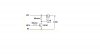
add the P channel mosfets in the 12V line (source), feed the gates of the fet's with the transistors going to ground, (add a 10k pull up resistor to the fet gates) feed the fet outputs (drains) to the coils.
ronv..... you are correct. D1 is backwards in my schematic, sorry.
Also, diode has a 40v & 20a rating. I apologize for my mistakes.
Thank you Joe G for your suggestion. If it's not too much trouble, could you post the schematic of your suggested circuit. I am a novice and need all the guidance people are willing to give.
Can you tell us the purpose of the circuit? Is it for providing a regulated voltage/current to the coils? Or are the coils just a convenient load for testing the supply? Or are the coils motor windings? Or........?
Can you tell us the purpose of the circuit? Is it for providing a regulated voltage/current to the coils? Or are the coils just a convenient load for testing the supply? Or are the coils motor windings? Or........?
Besides the FETs being upside-down, that isn't quite the circuit Joe suggested and it won't be suitable if you need to switch the FETs on and off rapidly. What signal are you applying to the input?
Besides the FETs being upside-down, that isn't quite the circuit Joe suggested and it won't be suitable if you need to switch the FETs on and off rapidly. What signal are you applying to the input?
MOSFET's upside down? Where did I go wrong? Those are P- Channel FET's right? As for Joe G's circuit, I thought I did what he said but you are the person of knowledge, not me. That's why I'm here..... to get the help I need. FET's do need to be switched on and off rapidly.
My thought was PNP transistors, with the coils driven from the collectors - giving far less loss - darlingtons are high loss devices anyway, and not terribly suited to switching applications (as the collectors are joined together there's not enough drive for the output section).
To maintain the HIGH = ON switching format, simply use an NPN transistor to feed the PNP's, also giving you much better base drive. There should also be low value balancing resistors in each PNP emitter (as there should have been in the original NPN emitters).
This site uses cookies to help personalise content, tailor your experience and to keep you logged in if you register.
By continuing to use this site, you are consenting to our use of cookies.


 , could it be the reason for needing 40 amps????