AllenPitts
Member
Hello ETO forum,
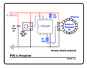
Working on light object that uses a PIR to trigger
a microcontroller, which operates a Adafruit
Neopixel 16 ring.

Presently the LED display operates when triggered by
the PIR for a minute as timed by the ATtiny85
microcontroller.
An improvement to the system would be
for the user, if desired, could override the PIR
and turn the Neopixel ring with a rocket switch
and so the LED display would operate until the
switch was toggled.
But because I am an architect, not an EE, the placement
of the switch is a mystery.
It would seem that the switch would be placed
in the circuit before power reaches the PIR
but that would simply make the whole system
be either on or off.
So it seems the switch should, when open,
allow the PIR and timer to govern. but
when the switch is operated, bypass
the PIR, but not the microcontroller
because the ring needs data.
Perhaps the solution is to use the
microcontroller logic to say, if
the PIR is triggered but there is no
signal from the PIR at the MC
(because the switch has opened
the PIR out trace to the MC)
then turn on the ring until
the signal is returned.
Although that would require the
PIR to be retriggered for the
ring to go off.
Is there simpler electronic solution
that would not require a
microcontroller logic solution?
Or a solution that uses the MC
logic but does not require the
PIR to be retriggered?
Thanks.
Allen Pitts
Working on light object that uses a PIR to trigger
a microcontroller, which operates a Adafruit
Neopixel 16 ring.
Presently the LED display operates when triggered by
the PIR for a minute as timed by the ATtiny85
microcontroller.
An improvement to the system would be
for the user, if desired, could override the PIR
and turn the Neopixel ring with a rocket switch
and so the LED display would operate until the
switch was toggled.
But because I am an architect, not an EE, the placement
of the switch is a mystery.
It would seem that the switch would be placed
in the circuit before power reaches the PIR
but that would simply make the whole system
be either on or off.
So it seems the switch should, when open,
allow the PIR and timer to govern. but
when the switch is operated, bypass
the PIR, but not the microcontroller
because the ring needs data.
Perhaps the solution is to use the
microcontroller logic to say, if
the PIR is triggered but there is no
signal from the PIR at the MC
(because the switch has opened
the PIR out trace to the MC)
then turn on the ring until
the signal is returned.
Although that would require the
PIR to be retriggered for the
ring to go off.
Is there simpler electronic solution
that would not require a
microcontroller logic solution?
Or a solution that uses the MC
logic but does not require the
PIR to be retriggered?
Thanks.
Allen Pitts