I’m investigating using the open circuit voltage of a small PMDC machine to measure the input speed to the shaft. The actual project relates to measuring the speed of a swinging pendulum.
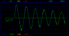
The PMDC generator is connected to the rotating hinge of the pendulum and the open circuit voltage of the generator is recorded using a data logger. I’m getting the expected output as shown below but I’m not sure how to convert the voltage to the speed.
I know Voltage Speed, but I’m not sure how to calculate the other parameters using the information I have to complete the equation and make the speed the subject of the equation.
I’m using equations for separately excited DC machines from a book “Electric Machinery Fundamentals” – Stephen J. Chapman.
From the equation Ea = Vt – IaRa where Ea is the internal voltage and Vt is the terminal voltage, I’m assuming that open circuit voltage (which is what I’m measuring) is equal to the terminal voltage as no current will be flowing. If this is true then Ea = Vt.
Ea = K’Φn where n is the speed. Can I work out K’Φ and from the information listed below? Or by using it as a motor can I work out the values?
Measured speed as motor (no shaft load):
6V -> 72 rpm
9V -> 108 rpm
12V -> 144 rpm
Equations from book:
K = ZP/ 2(Pi)a
a = number of current paths
P = Number of poles
Z = number of conductors
Information from manufacturer:
Motor type (PM, Series, Shunt), PM
permanent magnet flux (if PMDC),
The exact permanent magnet flux is hard to provide for 5P motor. The center Gs is 1100+/-5%
armature/field resistances, ---
number of poles, 5P
armature winding type (duplex lap-wound, simplex wave wound, etc), simplexlapwinding
number of armature coils/turns per coil, 32T
resistance per turn 0.34 ± 10%Ω
Why I’m measuring the speed using this method instead of other means is a long story but I’m stuck with it and I’m committed to it.