Continue to Site

Welcome to our site!

Electro Tech is an online community (with over 170,000 members) who enjoy talking about and building electronic circuits, projects and gadgets. To participate you need to register. Registration is free. Click here to register now.

  • Welcome to our site! Electro Tech is an online community (with over 170,000 members) who enjoy talking about and building electronic circuits, projects and gadgets. To participate you need to register. Registration is free. Click here to register now.

wireless fishing alarm

Status
Not open for further replies.

thomaspav

New Member
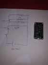
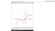
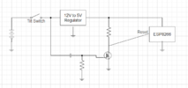
hello everyone from Greece. I have a simple circuit for a fishing alarm. Basically i use a tilt switch for sensor, two leds and one buzzer. Its a simple circuit with low cost materials. I would like to go it to the next step. I will make 6 of this circuits for my fishing rods. Here is my question. How can i make a simple rf system to have receiver for each rod ? I need about 200meter distance. Also i would like to have separate signal for each transmitter to recognise witch rod has a bite. I post a video of an example https://www.aliexpress.com/item/4000341609254.html
 
If you feed the 5V pin on the module and leave USB connector unplugged that
will prevent the prog interface from consuming power.


You may have already seen this....:

1674164124893.png


Use of timer to wakeup : https://www.electronicshub.org/esp8266-deep-sleep-mode/


Regards, Dana.
 
Last edited:
If you feed the 5V pin on the module and leave USB connector unplugged that
will prevent the prog interface from consuming power.


You may have already seen this....:

View attachment 139996

Use of timer to wakeup : https://www.electronicshub.org/esp8266-deep-sleep-mode/


Regards, Dana.
Hello Dana. Yes i already have seen that article. What do you think about the esp12E? Can i use it instead of the larger esp8266?
 
Hello Dana. Yes i already have seen that article. What do you think about the esp12E? Can i use it instead of the larger esp8266?
Short answer no reason not to. You have to provide programming interface, many
ways of doing this.


Regards, Dana.
 
Hello. Im almost done with the sketch for the transmitter but i have a problem. So i need to put the transmitter to deep sleep to keep the battery alive as much as i can. The best way to wake up the esp is with external mode. BUT i need with some way to do it from the rst pin. So how can i do this? I break my head but i cant find a solution. How to wake up the esp when my circuit is close? I will give different source of power to the circuit and different to the esp. How can i do the rst pin goes LOW? :/
esp8266-external-wake-up-micropython_bb.png
 
Same as in your diagram, just connect your switch that indicates a bite across the reset button.

Mike.
Edit, Or, use the same circuit on the "wake up" pin with the push button replaced by your bite indicator switch.
Edit2, the circuit you have there has a pullup resistor to hold the pin high and a push button to connect it to ground. You can also use a pulldown resistor (connected to ground) and have the switch make it go high.
 
Timer based....


Regards, Dana.
 
Last edited:
Hello thanks for the reply. Here is a hand made present of the circuit. As I read here https://www.electronicshub.org/esp8266-deep-sleep-mode/ in order to wake up with external source I need to make the RST PIN LOW. The only information I can get from my circuit is when the tilt sensor is working. Could you please explain how to use the circuit to wake up the esp? Also if I understand correct I must connect the RST to GROUND. Thanks for your help.
 

Attachments

  • 31340387-C87B-4D39-BBDD-91BB2C1FD2FE.jpeg
    31340387-C87B-4D39-BBDD-91BB2C1FD2FE.jpeg
    837 KB · Views: 133
You need to pull the reset line low - connect it to ground. If you intend to keep your existing circuit then you'll need a transistor or relay. To keep it simple, use a relay. Have the relay coil connected same as your buzzer/LED and have the contacts ground the RST pin.

The two circuit grounds will need to be connected together for this to work or you can connect the relay contacts across the push button.

One problem with this is that the RST pin will be help at ground and permanently reset (to simulate this simply hold your reset pin down, nothing will happen until you release it). To stop this a capacitor should be placed in series with the relay contacts. Something like 10 uF should suffice, your diagram shows a 10k resistor, is this correct? The positive end of the capacitor (assuming electrolytic) should connect to the resistor side.

Mike.
 
Wire a hi valued R as a pullup on RST, connected directly to battery. Say 10 K. Also connect a small signal diode from RST to ESP8266 Vdd, cathode to RST, anode to Vdd. Then use a V divider from load side of tilt thru an inversion, like into a mosfet gate, like 2N7000, its gate, its drain connected to RST, its source to ground, to pull down RST pin to generate - going pulse into RST.

.....Its seems this wants to be a negative going pulse.......possibly a RC differentiator into 2N7000 gate....

Regards, Dana.
 
Last edited:
Something like this (you look up RST pulse width requirements)

1674437926785.png


If tilt sensor produces a lot of "bounce" then you will have to use a one
shot to clean up the RST pulse. CMOS logic or RS F-F.


Regards, Dana.
 
Last edited:
If tilt sensor produces a lot of "bounce" then you will have to use a one shot to clean up the RST pulse
I imagine that a fish on a hook is going to cause the rod to bounce lots and the tilt switch to get triggered lots and the ESP to be reset lots. Sounds like a rethink is needed.

Mike.
 
Processor starts and disables its own reset circuit.....temporarily......performs the
messaging, then checks for more bounce before re-enable, or uses period delay
or processor does not go back into sleep until host (user) presses on hostESP8266
a button to transmit message to go back to sleep (after removing fish).....

Regards, Dana.
 
Hi Dana and Mike. I am sorry for the delay. I've been trying nearly a couple of hours to understand your sketch but I'm not experienced enough to understand it completely. Let me ask a few questions by writing on your sketch. As I understand the esp to wake up has to make the first pin go to 0v and back to 3.3v. I don't remember if I mentioned it but the external power of the esp is via an 18650 battery with an LDO refulator. Thanks in advance for your time Dana.
 

Attachments

  • 1674437926785.png
    1674437926785.png
    94.8 KB · Views: 117
1) The ESP8266 Vdd supply shown is your 3.3V LDO output
for the ESP8266.

2) The ground is the neg side of the battery, the common in
your diagram shown as right vertical leg of your schematic.

3) R2 C1 is a differentiator that takes the step 12 V turn on V from
the tilt sensor, and creates the + going edge into the MOSFET
gate. which turns it on, its drain going to ground, generating RST.
When cap charges from the 12 V step the Vgs of MOSFET returns
to 0 and MOSFET turns off returning the RST pin to 3.3 V.

Remember you have to do the homework to figure out the RC time
constant to meet the min RST pulse width. I cant seem to find a min
RST pulse with, so you may have to experiment with differentiator
values. Guess is 1 - 100 uS. You may set up on bench a switch to
turn on power and look at RST pin on module and see what its
PW is. The Nodemcu module has the following values for RST pin
(nRST) :

1674518815580.png


In my simulation that produces ~ 10 uS, but the circuits and thresholds
of devices different than Nodemcu. Do the bench testing over some Vdd
variation to make sure your solution is good.


Regards, Dana.
 
Last edited:
I didn't know it could do that. I thought the reset pin was hardware and would always reset the chip.
You could very easily brick it by disabling the reset circuitry.

Mike.

Using a gate, like a NAND or AND (whatever logic works for design) after reset occurs
and returns to Vdd and processor takes over no reason one could not use GPIO into
gate to prevent another edge from a bouncing source to generate another reset. Then when
processor finishes its biz re-enable the gate in order to take another reset. Of course pullups
and power supply ramp behavior all have to be considered, and GPIO state when in "no mans
land" for the case Vdd no longer meeting minimum.

Might even be prudent to use gates with Schmidt inputs.....may even be processor has Schmidt
on its RST input.....

Regards, Dana.
 
Hello Dana. Im trying to understand the principles of your sketch. I understand something like that on the photo. Its my first time on this path and it takes me some time to understand all that you write. Thanks in advance for your work that you effort here.
E7EDC7C0-28DD-44C5-B6A4-354D1EE06AC3.jpeg
 
Last edited:
1674690832686.png


The input to capacitor can be input to 12 V to 5 V reg or to its output, the latter
probably better.

This does not show bypass C's you normally put at input and output of regulator to ground,
which you should do.

Now for some additional insight. When the tilt switch fires if it has bounce you will
have to debounce that with additional circuitry so you can send a clean pulse to gate
of 2N7000. Additionally when ESP8266 finishes reset and goes into normal operation
you need to log into network and send data to host ESP8266. It can take secs to log into
network, and if tilt sensor was activated again the esp8266 might get terminated prematurely.
So one would want the ESP8266, first thing when it starts, to disable any further reset
inputs. You would need a gate in RST signal path to disable any further resets while it
does its thing. And you would need a big enough cap on 3.3V to it to keep it in power
(because the tilt switch no longer supplying power) so it can fin its job.

Some engineering and test has to go on here. Can you hook up with a designer/EE or tech
friend to get this done ?

Regards, Dana.
 

Attachments

  • 1674690602131.png
    1674690602131.png
    15 KB · Views: 124
Last edited:
Status
Not open for further replies.

Latest threads

New Articles From Microcontroller Tips

Back
Top