Electro Tech is an online community (with over 170,000 members) who enjoy talking about and building electronic circuits, projects and gadgets. To participate you need to register. Registration is free. Click here to register now.
Welcome to our site! Electro Tech is an online community (with over 170,000 members) who enjoy talking about and building electronic circuits, projects and gadgets. To participate you need to register. Registration is free. Click here to register now.
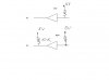
I found another schematics,which is a bit different.I Modified my programmer ant it works.
I attached the modifications i made.They are the same for Data,Clock and ACK line.
The pullup resistor is absolutely essential, as the buffers are open-collector, and (as expected) it is shown on the original Bob Blick circuit - I just checked the link in your first post!.
This site uses cookies to help personalise content, tailor your experience and to keep you logged in if you register.
By continuing to use this site, you are consenting to our use of cookies.