Sorry Mike, but I can't answer your question about the impedance of the meter. The one I've been using is a Fluke digital multimeter 8022A that I've had for many years.
I looked up the specs on Fluke's web site. In the DCVolts mode, the input impedance is 10megΩ, meaning that the leakage in your battery bank which is "earthing" the bank is pretty high. Probably just moisture on the surface of the battery cases

I am beginning to suspect that there is some problem coming to the surface in the battery bank because these days it won't hold a charge as long as it did a few months ago; maybe the connections need to be checked out; maybe a battery has gone "bad". This though is another subject and not the 555 controller circuit we've been building.
Setting up a charge controller is a science unto itself, and the best authority is the company ("Siyuan"?) that supplied your batteries. If you don't already have it, visit their web site and download the product manual specific to your batteries.
If you suspect you have a bad battery, use your fluke to measure each 12V battery in your series string. If you see one of the 12V batteries that has a terminal voltage of ≈11V instead of ≈13V, then you might have a bad cell in that particular battery. At any given state of charge, all of your 12V batteries should have nearly the same terminal voltage; a difference from battery to battery is a sign of trouble. While doing this, look for a broken case. I suspect this could be where your battery bank is finding its mysterious ground.
I'll take your advice and change the capacitors to eliminate the ripple. After that all should be set. I've adjusted the resistor values and installed a couple of trim pots; all are fairly beefy components to handle the power. The indicator LED has been removed and the output from pin 3 now goes to drive the low voltage relay. When the circuit is connected the output is high and so the relay will make contact, this then is connected to a second more powerful relay that switches the house supply between inverter output and the national grid.
I assume that when the pin 3 output is high the batteries are charged up and that the system can be left connected to the inverter/battery bank? When the battery output level falls low (below 240v) the 555 will trigger the two relays to switch the house across to the national grid and allow the batteries to charge up again without any load. When the batteries reach 260v the system will trip again, pin 3 will go high, the relays will change state and the batteries will begin to discharge via the inverter as the house uses up energy.
If this isn't the way things work please point me in the right direction! I'll try wiring it up today and the only way I can really try it out is to wait for low voltages or high wind.
I'll keep you posted.
Just to be clear (ala Omaba

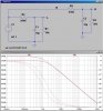
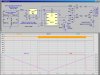
), when the battery voltage is ≤ 240V, pin 3 of the 555 goes HIGH, and the relay pulls in. It stays pulled in until the battery voltage ≥ 260V, at which point pin 3 of the 555 goes LOW and the relay drops out. Look at the updated simulation I have attached.
I updated the diagram to reflect some of the issues we have been discussing. Note the size of C3. With 13Vrms on the transformer secondary, if this capacitor is smaller than 470uF, the unregulated voltage sags below the dropout voltage of the LM317, and there is much ripple on the 12V line!
This depends on the resistance of the 12V relay. If your relay's coil resistance is higher than 120Ω, then C3 could be smaller.
")