Continue to Site

Welcome to our site!

Electro Tech is an online community (with over 170,000 members) who enjoy talking about and building electronic circuits, projects and gadgets. To participate you need to register. Registration is free. Click here to register now.

  • Welcome to our site! Electro Tech is an online community (with over 170,000 members) who enjoy talking about and building electronic circuits, projects and gadgets. To participate you need to register. Registration is free. Click here to register now.

Wind turbine battery controller

Status
Not open for further replies.
Hello Again,

Still not much luck I'm afraid. I followed your suggestion Mike and I connected the circuit to a 12v transformer instead of using the wind turbine controller power supply. I then connected the negative side of the battery bank to the ground of the 555 circuit. However, when I connected the positive side of the battery bank to the circuit there was a large spark and quite a bit of smoke. It looks like the voltage division resistors have got cooked, probably not surprising since they were connected directly between the two battery bank terminals...

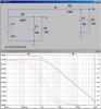
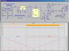
I reran the simulation and checked the power dissipation in R1 and R3. It is only 120mW worst case, so even a 1/4w resistor should have been ok. I suspect that the resistors you used for R1 and R3 could not stand ~240V, so here is my suggestion: Put three or four 1/4W metal film resistors in series, such that R1 totals 630K and R3 totals 590K. This will keep the voltage across each resistor to less than a hundred volts.**broken link removed**. What style of resistors did you use for R1 and R3?

The "transformer" used to power this circuit should be a mains-powered plug-in charger or power supply that puts out 15V to 20V DC. That goes into the input of the LM7812 voltage regulator to make the regulated 12V to power the 555. The accuracy of the trip points is directly a function of the voltage at the 555 pin 8. If this voltage is 3% low, then the trip points will also be 3% low, etc.
 
Last edited:
OK Mike, I follow your what you're saying. The resistors I used were all 1/8 watt 5% and must have been far too weak for the circuit. I'll have to look around to see what else I've got, otherwise I'll have to order some sturdier parts.
The transformer was a mains powered device giving out just over 13 vdc; it was connected to the regulator as in your design.
I'll continue in the morning and keep you up to date as I go along.
 
...

As I mentioned in an earlier reply, neither of the battery bank cables are tied to the wind turbine controller ground; there's about 100 volts difference. However, I have tried putting a pair of voltage dividing resistors between ground and the terminal marked 'L'. When I first tried this the 100v dropped to almost zero; I don't know why, but the system continued to function, nothing got hot or started to smoke. The right resistors will have to be selected to obtain a 4v or 8v output but it might be possible to get the circuit working like this. I'm just guessing of course, I'm really out of my depth so if someone's got some sound advice I'd be glad to hear it!

Thanks everyone for your consideration and helpful ideas.

Ok, I think I understand what is going on. Neither the battery bank, nor the generator, nor the voltage sensing circuit inside the windmill controller is tied to earth ground. The entire system is "floating". The 100V difference between one end of the battery bank and the "ground" on the controller that mysteriously went away when you were probing around is probably due to some very high-impedance leakage path somewhere inside the battery bank.

I'll bet that if you measured the voltage from the controller ground to the negative side of the battery bank, you might see -100V, while from ground to the positive side of the battery you might see +140V, such that the sum of these two readings would come close to the measurement from Bank- to Bank+ of 240V.

This is somewhat of a surprise to me. I thought that either Bank+ or Bank- would be connected to earth ground. However, this does not matter if the 555 voltage sensing circuit is totally isolated in its own right.

A caution: The secondary winding in the small transformer that you are using to power the 555 circuit will be tied to Bank-. If Bank- is not at earth potential, then whatever voltage Bank- sits at will appear between the primary and secondary windings on your transformer. This should be ok, because most of those consumer grade power supplies (wall-warts) are tested to something like 1000V isolation between the windings, but I just thought I would mention this to you.
 
OK Mike, I follow your what you're saying. The resistors I used were all 1/8 watt 5% and must have been far too weak for the circuit. I'll have to look around to see what else I've got, otherwise I'll have to order some sturdier parts.

If I had to buy them, I would order some physically larger resistors, like 1W size. They seem to stand off higher voltages than 1/8 or 1/4W ones do. I would also break R1 (630K) into two separate resistors, say 130K and 499K. Mount the 130K on your circuit board, but mount the 499K off the board right on the Bank+ terminal (use heatshrink tubing on the floating connection off that resistor) That way, you do not have the 240V on your handwired board (only 55V). Even if you slipped with a meter probe, the 499K resistor between Bus+ and your board would limit the current to a safe value. Do the same for the R3 line.

I would put the trim pots at the 555 end of the R1/R3 chains. That way you are not apt to hit the 240V while you are tweaking them.

The transformer was a mains powered device giving out just over 13 vdc; it was connected to the regulator as in your design.
I'll continue in the morning and keep you up to date as I go along.
This raises another issue. The LM7812 regulator has a dropout voltage of 2V, so to get the rated 12V out, the input voltage must be 14V or higher. If the voltage sags below 14V, the 7812 might be dropping out of regulation.
If it is close, try putting a larger electrolytic filter capacitor (say 1000uF at 20V) across the input to the LM7812. There might already be a capacitor inside your Wall-Wart, but if there isn't, adding one might help get the voltage a volt or so higher.
 
Hi Mike,

You're right about the battery voltage measurements. Accross the bank terminals you'll usually get a reading of around 240V, but measuring from the positive terminal to the controller ground the figure is around 100v and from negative to ground its closer to 120v. Why the two figures don't even add to 240v is beyond me but that's what I keep getting from the voltmeter.

I went through the 555 circuit today and rebuilt it. I dug out my most powerful resistors and chained them all in series as you suggested; I was able to obtain exactly 590k and 630k to divide the incoming signal. I didn't add any trim pots at this time because I don't know their power ratings. I don't have a 7812 but I am using a transformer running through a LM317 circuit that puts out exactly 12v.

I took the revised hardware out to the wind turbine controller a few minutes ago and tried wiring it up. First attempt ended in another big spark and a loud bang! However, after the smoke had cleared I was able to see what had happened; it was my own fault. The battery bank is driven directly from the turbine generator and as a result the voltage has an ac ripple. I had included a large electrolytic capacitor across the input to the PCB to try to eliminate this fluctuation; the bang and the smoke were due to this cap exploding. As nothing else seemed to be damaged (except one terminal that had been completely melted off the end of input lead!) I removed the remains of the cap and tried reconnecting for a second time..... ....all seemed to work OK! No sparks or smoke. The LED glows from the pin 3 output, and yes, it looks like it's working! Now I'll need to add those trim pots to try and check the trip levels.

I read your last message and by chance the resistors I added are all mounted far away from the 555 at the opposite end of the board. They're large components and there was no room to place them where the original resistors had been situated. I think it'll be fairly safe in this configuration.

I'll now try adding the trim pots, put the relay into the circuit, connect it all up and keep you informed. The project is making progress and I think I can now stop worrying about the sparks and the explosions! Thanks again for all your help.
 
What is the input impedance of the voltmeter you are using to measure the battery terminals? I believe that the reason the two readings do not add to 240V is because the battery bank "ground" is being defined by a very high impedance leakage path to earth ground.

Just the act of connecting your voltmeter between earth ground and Bank- or Bank+ draws enough current(through the meter) to effect each reading. If you owned two identical meters and made the two measurements simultaneously, the two readings would add exactly to the bank voltage. Making the two reading serially with one meter shifts the first reading one way, and the second reading shifts it the other way ;)

If you want to "filter" the voltages presented to the comparators inside the 555, then increase the size of C4 and C5. With the present values of 0.1uF, the -3 db corner frequency above which any ripple on the battery bus is attenuated is about 70Hz. If you increased C4 & C5 to 10uF, for example, the corner frequencies shift down to about 1Hz, providing about about 30db of additional attenuation at a ripple frequency of 100Hz. Look at this:
 

Attachments

  • HiLoFilter.jpg
    HiLoFilter.jpg
    156 KB · Views: 421
Sorry Mike, but I can't answer your question about the impedance of the meter. The one I've been using is a Fluke digital multimeter 8022A that I've had for many years. I am beginning to suspect that there is some problem coming to the surface in the battery bank because these days it won't hold a charge as long as it did a few months ago; maybe the connections need to be checked out; maybe a battery has gone "bad". This though is another subject and not the 555 controller circuit we've been building.

I'll take your advice and change the capacitors to eliminate the ripple. After that all should be set. I've adjusted the resistor values and installed a couple of trim pots; all are fairly beefy components to handle the power. The indicator LED has been removed and the output from pin 3 now goes to drive the low voltage relay. When the circuit is connected the output is high and so the relay will make contact, this then is connected to a second more powerful relay that switches the house supply between inverter output and the national grid.

I assume that when the pin 3 output is high the batteries are charged up and that the system can be left connected to the inverter/battery bank? When the battery output level falls low (below 240v) the 555 will trigger the two relays to switch the house across to the national grid and allow the batteries to charge up again without any load. When the batteries reach 260v the system will trip again, pin 3 will go high, the relays will change state and the batteries will begin to discharge via the inverter as the house uses up energy.

If this isn't the way things work please point me in the right direction! I'll try wiring it up today and the only way I can really try it out is to wait for low voltages or high wind.
I'll keep you posted.
 
Here you go. I used a LED as a temporary load. You can use a small relay. I would put a snubber diode around the relay coil. If you want it to be ON when the LED is OFF, you can return the other end of the relay to 12V instead of ground. Use a 12V relay with a coil resistance greater than about 100 Ω

doesn't the 555 have a "push pull" output meaning that the diode would short the out put when it is "off" i may of course be talking out of my hat
 
doesn't the 555 have a "push pull" output meaning that the diode would short the out put when it is "off" i may of course be talking out of my hat

Hello Thunderchild,

If a 120Ω relay coil is connected between pin 3 of the 555 and ground, and pin 3 is HIGH, the 555 sources current from pin 3 through the relay coil to ground, actually about E/R=12/120=0.1A=100mA. If a diode parallels the relay coil such that the cathode end is at pin 3, then the diode is reversed biased by ≈12V, and only reverse leakage current flows though the diode. If pin 3 of the 555 is LOW, there is 0V across the coil and the diode, and no current flows through the diode. Look at the revised schematic I'm posting in my next response to vielle568.

The only time any significant current flows through the diode occurs just as the 555 switches from HIGH to LOW. Without the diode, the inductive spike from the relay coil would try to drive 555 pin 3 to a negative voltage. The diode clamps that voltage to no more than -0.65V (forward conduction voltage of a Si Diode).
 
Sorry Mike, but I can't answer your question about the impedance of the meter. The one I've been using is a Fluke digital multimeter 8022A that I've had for many years.
I looked up the specs on Fluke's web site. In the DCVolts mode, the input impedance is 10megΩ, meaning that the leakage in your battery bank which is "earthing" the bank is pretty high. Probably just moisture on the surface of the battery cases:D


I am beginning to suspect that there is some problem coming to the surface in the battery bank because these days it won't hold a charge as long as it did a few months ago; maybe the connections need to be checked out; maybe a battery has gone "bad". This though is another subject and not the 555 controller circuit we've been building.

Setting up a charge controller is a science unto itself, and the best authority is the company ("Siyuan"?) that supplied your batteries. If you don't already have it, visit their web site and download the product manual specific to your batteries.

If you suspect you have a bad battery, use your fluke to measure each 12V battery in your series string. If you see one of the 12V batteries that has a terminal voltage of ≈11V instead of ≈13V, then you might have a bad cell in that particular battery. At any given state of charge, all of your 12V batteries should have nearly the same terminal voltage; a difference from battery to battery is a sign of trouble. While doing this, look for a broken case. I suspect this could be where your battery bank is finding its mysterious ground.

I'll take your advice and change the capacitors to eliminate the ripple. After that all should be set. I've adjusted the resistor values and installed a couple of trim pots; all are fairly beefy components to handle the power. The indicator LED has been removed and the output from pin 3 now goes to drive the low voltage relay. When the circuit is connected the output is high and so the relay will make contact, this then is connected to a second more powerful relay that switches the house supply between inverter output and the national grid.

I assume that when the pin 3 output is high the batteries are charged up and that the system can be left connected to the inverter/battery bank? When the battery output level falls low (below 240v) the 555 will trigger the two relays to switch the house across to the national grid and allow the batteries to charge up again without any load. When the batteries reach 260v the system will trip again, pin 3 will go high, the relays will change state and the batteries will begin to discharge via the inverter as the house uses up energy.

If this isn't the way things work please point me in the right direction! I'll try wiring it up today and the only way I can really try it out is to wait for low voltages or high wind.
I'll keep you posted.

Just to be clear (ala Omaba:p), when the battery voltage is ≤ 240V, pin 3 of the 555 goes HIGH, and the relay pulls in. It stays pulled in until the battery voltage ≥ 260V, at which point pin 3 of the 555 goes LOW and the relay drops out. Look at the updated simulation I have attached.

I updated the diagram to reflect some of the issues we have been discussing. Note the size of C3. With 13Vrms on the transformer secondary, if this capacitor is smaller than 470uF, the unregulated voltage sags below the dropout voltage of the LM317, and there is much ripple on the 12V line!
This depends on the resistance of the 12V relay. If your relay's coil resistance is higher than 120Ω, then C3 could be smaller.
 

Attachments

  • Hilo555.jpg
    Hilo555.jpg
    194.7 KB · Views: 396
Last edited:
Hello Mike,

On your first point concerning the batteries and their "earthing" problem, you could be right about the damp causing the power to leak. I'm restoring an old stone built farm, and the electrical equipment is located in one of the outbuildings (a pigsty). The batteries are in a large insulated case, but even so the damp seems to penetrate in spite of the ventilation. At first glance the fluid levels seemed OK but I haven't checked everything thoroughly. One thing that did catch my attention was that all the terminals seem to have turned white with some sort of mold over the cold winter months. I'll try cleaning it off and also checking out the voltages in case there's any faulty cells.

Thanks for the revised schematic. The circuit I've built is exactly the same except that the relay I have is only 6v and so I have pin 3 connected to the base of a transistor that triggers the relay at a lower voltage. Yes, it all works. The capacitor for the LM317 is 1000uF so it should be OK; the voltage is up at 12v and the relay toggles alright when the power is turned on.

I have since wired in a cable to bring 230VAC into the wind turbine controller to power the transformer. I've also installed another cable going from the controller across to the power input panel for the house where I've mounted the two relays; one to switch the house over from the national grid to the inverter output and the other to act as the toggle. I should be able to get the installation finished tomorrow and see how it works in practice. I'll keep you posted.
 
Last edited:
Hello Again,

Well the 555 circuit is finally in place in the wind turbine controller. It seems to be wired up correctly because there were no sparks or explosions today. The voltage division resistors are mildly warm, but apart from that nothing else is getting hot or smoking. It's mounted in a plastic case just to be safe; the trim pots are mounted on the side with knobs attached. At the moment the relay is pulled in keeping the load (the house) tied to the inverter/battery bank. There's a fair amount of wind here at the moment and so the batteries keep on charging. I can't say if yet the new circuit triggers when the batteries run low on energy.

After the 555 circuit was put in place I took a good look at the battery bank. I dismantled the cables and took all the batteries out from the case. I noticed quite a bit of damp where the batteries had been sitting. Could this have been the cause of the energy leak? I don't know if it was acid or condensation but I has now made a wooden lattice to keep the batteries off the case floor and to allow better ventilation. The terminals were white with some mild corrosion; they're clean now and all the batteries are back in the case and reconnected to the system. I checked the battery voltages; every one was somwhere between 12.3 and 12.7 volts. None of the twenty batteries were down in the 11 volt region so I assume all are OK for the time being.

I took a current reading from the battery bank cable and it showed that the batteries were being charged. Obviously the inverter and the house were taking less load than the incoming power from the generator. It seems unlikely that the inverter is drawing a high current and causing the problem. The system is up and running at the moment and all I can do is to wait and see if the batteries hold out any longer.
 
Last edited:
Hello Vielle,
I only saw this thread today for the first time and i am right into making my own wind generators. That 3kw downwind turbine of your from china is something a mate of mine is looking at to buy himself. I have sort of read through this whole thread but missed some important infomation.

Ok you say this is a 3kw turbine... What voltage does the generator is it 3 phase AC and does the chinese controller rectify the generator output.

You did say you had 20 12 volt batteries in series for 240 volts DC. what inverter do you have that takes a 240 volt DC input as I've never heard of such a beast and that kind of high DC voltage is lethal. A 12 volt battery is fully charged when it's 13.8 volts which is 276 volts on a 240 volt DC batterybank. Also if you want your batteries to last I'd suggest not taking them under 12 volts.

As far as using a servo for furling I'd throw the thing as far away as you can, the blades should self regulate the blade speed or a simple rpm sensor could short the AC windings with no harm done. Another solution if possible is installing a disk brake on the rear of the alternator and when a preset speed is attained the brake can engage. This feature can also stop the generator when a huge storm is approaching.

I have made my own charge controller using a LM358 Opamp and 2 169amp fets in parrallel to dump any excess load when my batteries are full and the genny is going flatout.

If you would like some help I'd be glad chime in mate

Cheers Bryan
 
Last edited:
Hello Bryan1,

The system I have does not rectify the output current. I have twenty 200Ah batteries (acid filled cells) that are connected in series to form the battery bank; these are charged by energy from the wind turbine and from some solar panels. These pass through a controller that has a couple of functions: First it signals when the batteries are above or below voltage (but does nothing to rectify the situation. Second it is connected to a dogvane and an anemometer that are used to control a servomoter that turns the generator into the wind.

The output from the controller is fed into an 50Hz sine wave inverter and the output is connected to the house. I've been gaining help from this forum to build a control circuit to switch from the wind turbine system to the national grid when the batteries are low and to reconnect when the batteries have sufficient charge.

The Chinese company make many different models of wind generator, solar panels, batteries and all the necessary equipment; the prices are very low and they have a lot to offer. It is a big company too, so don't feel nervous about purchasing from these people; I had no trouble with my order, all the equipment was delivered to my door in France. If you wish to contact this company for more information then here's the information you need: The contact engineer is called Cary, mention my name, Bryan (like you), the company name is Wuxi Kingship, and Cary's email is :
windpower02@gmail.com

It is not possible to add a disc brake behind the hub on this generator so I'll have to rely on the current design. I'd be interested to see your design for the excess load dump.
Thanks
 
Message to MikeMl,

Hi Mike, The batteries appear to be working a lot better after the clean up treatment yesterday. They were reading just a few volts down after last night (248v from 252v). Previously the batteries would dive to below 230v overnight and the system would crash. The system's running as it should be and the 555 controller seems to be functioning correctly.

Thank you once again for all your help in this project.

Best wishes, Vielle568
 
Use a 555. Feed the Vcc pin with a 10V regulator. The trip points of the two comparitors will be 3.333V and 6.667V, respectively. Now make two voltage dividers off the sensed voltage input such that one produces said 3.333V when the sensed voltage is at your lower trip point, and the other divider so that it produces 6.667V when your sensed voltage is at your upper trip point. The 555 can drive a small relay, or buffer its output as ne

I built a battery charger using this trick. The two voltage dividers utilize trim pots, so the upper and lower trip voltages are easily adjustable. I can post an LTSpice schematic if you want.

Hey mike if you would could you post or send me your schematic for your battery charger, so that i have something to work off of with my project?
 
Status
Not open for further replies.

Latest threads

New Articles From Microcontroller Tips

Back
Top