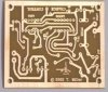
OK, so I decided on a simple charge controller circuit for my wind generator. I went with the one on this site; wind charge controller . It is the top most post for the charge controller by Thomas Miller. Anyways, I decided to recreate the circuit board shown in Eagle editor since there was no board layout image for download. I put the board together and fired it up with my bench variable supply. After noticing that I had missed a solder bridge and cooked at least the 4001 logic chip I decided to install IC sockets for better testing. I decided to test each part of the circuit separately.
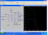
The first part of the circuit uses a common op amp voltage window detector circuit giving you a high and low trip point with an in-between voltage window. So to start the test, I set the supply at 12.5 volts and set the voltages at the test points to 7.25 for A and 5.9 for B. This should make the window between 11.8 and 14.5 volts. So I then set the supply for 10 volts and installed the LM339 leaving the 4001 out to check the comparator outputs. at 10 volts, the output at pin 1 was pulled low since it was below the low trip point, and pin 2 was high which it should have been. As I slowly ramped up the voltage and got past the 11.8 volt mark, both pins 1 and 2 read high which was good. I continued to ramp the voltage past the 14.5 volt mark (~16 volts) but pin 2 remained high and was never pulled low by the comparator. I then double and triple checked the voltages at the touch points and made sure that the voltages were also seen at the correct pins on the IC socket. I also verified the input voltage at the IC at ~8.06 volts which seemed to me to be in tolerance. Once all my voltages were verified, I had thought that I had also cooked the LM339. I had a couple new ones in the parts box and installed a new one. Low and behold, I got the same results, pin 1 was low below 11.8V and pin 2 never pulled low.
I figured that I would do some further research and come back to the comparator side of the circuit later and see if the RS flip flop part of the circuit was working. I did not have any more 4001 2 input NOR gate chips, but had a 4011 2 input NAND gate. Knowing that these are pinned the same I figured that they would work in a similar fashion when configured as an RS flip flop. I removed the LM339 and installed the 4011. When powered on with 12.5 volts, I had the red light on. I then used a jumper wire to manually pull pins 1 and 6 low alternately. As I did this, I was flipping between red and green lights telling me that the flip flop was working.
Now I am here. I am still left with the problem with the window detector circuit that is not working. Does anyone have any ideas as to what would cause pin 2 of the op amp chip to never get pulled low? I have triple checked the traces on the circuit board along with all the voltages at each pin. I have swapped in 3 other LM339 chips with the exact same results from each. I am at a loss....
")