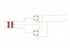
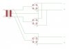
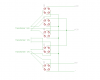
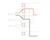
I have a 24V transformer and two 12V transformers. I need some 24V current and as much 12V current as possible.
I need a common ground. If I connect the grounds, is it still going to work? I'm a bit paranoid, because a cap just blew up in my face the day before yesterday, though I don't think the circuit was exactly like this.