yes it does work with your 47K modification... and with 100K but only with
2n2222 in metal can! i also tryed 2n3904 and it didn't worked... it lights stable i haven't tryed bc547..
1k resistor fills the capacitor too fast? why the schematic says 1K???
i don't see how LTspice can simulate such thing... it's an undocumented function...


")
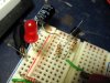
 hm: resistor, 100:mu: F capacitor and a BC547B with a RED led.