Electro Tech is an online community (with over 170,000 members) who enjoy talking about and building electronic circuits, projects and gadgets. To participate you need to register. Registration is free. Click here to register now.
Welcome to our site! Electro Tech is an online community (with over 170,000 members) who enjoy talking about and building electronic circuits, projects and gadgets. To participate you need to register. Registration is free. Click here to register now.
The LS part has a very wimpy high output current IOH. You will never be able to drive that circuit. Why not just use an OR gate? Also keep in mind HC can drive LS parts ok but LS is not always able to drive HC, so you should stick to one logic family. Also why is R6 on your FET? I don't think you want to drive 50 ohms.
Thank you Mike,
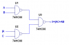
I am trying to keep parts count to a minimum. I could use an OR gate but that is another chip. I forgot to change the chip families to both HC, as suggested by audioguru, as was R6 also suggested. I want a simple battery operated electric lock to make a motor forward and reverse only stoping when the lock is locked or unlocked. For now, U is a momentary push button. B and C are phototransistors. Maybe I will switch to Light Sensitive Resistors. No, I don't want to drive 50 ohms. I want to use as little as power as possible for the circuitry. All the power should be used only when motor is on, and very little when it is stopped. Thanks for the help.
I would change R5 to 100 ohms.
If you don't need the extra gate, either connect the inputs to GND, or put it in parallel with the "output" gate to speed up MOSFET switching.
How much current does your relay require?
EDIT: I just saw your last post. R1 and R2 should be around 10k. If you don't get solid "0" levels at B and C, change R3 and R4 to 10k, and R1 and R2 to 100k.
This site uses cookies to help personalise content, tailor your experience and to keep you logged in if you register.
By continuing to use this site, you are consenting to our use of cookies.