Electro Tech is an online community (with over 170,000 members) who enjoy talking about and building electronic circuits, projects and gadgets. To participate you need to register. Registration is free. Click here to register now.
Welcome to our site! Electro Tech is an online community (with over 170,000 members) who enjoy talking about and building electronic circuits, projects and gadgets. To participate you need to register. Registration is free. Click here to register now.
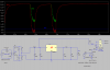
That still sounds far too high, even for a small transformer.
The SPICE model is still inaccurate, it should have a slightly higher secondary voltage than 9V, probably by about 30% higher. At full load the voltage will be 9V because of the copper losses.
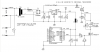
Swap D3 from 1N4002 to a much faster 1N4148, it's still plenty big enough for that task as the relay back emf won't have much energy. Never use a slow relay diode with a micro circuit! D4 is not needed.
Replace D2 with a big cap, at least 470uF, this will decouple any relay current surge from your main supply AND supply the main current pulse to let the relay pull-in. Then you can increase the value of R3 to reduce relay operating (hold) current to a value less than its pull-in current but safely above its drop-out current. This reduces FET heating AND reduces the back emf energy from relay turn off AND provides greater isolation between relay and PSU/micro in general.
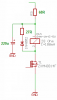
Get rid of the inductor after the regulator (blech!), replace with a small resistor for filtering (assuming you are not using ADC and dont need a perfect 5.0v) drop about 0.1v on the resistor at normal micro operating current and add a 10uF tantalum across C5.
Finally if you are just driving the FET on/off (not pwm) then replace R2 with a safer value like 2k7 which will save your micro if the FET lets go and you get full PSU voltage where its gate used to be you will only get a couple mA into the micro pin internal protection diode.
Swap D3 from 1N4002 to a much faster 1N4148, it's still plenty big enough for that task as the relay back emf won't have much energy. Never use a slow relay diode with a micro circuit! D4 is not needed.
Replace D2 with a big cap, at least 470uF, this will decouple any relay current surge from your main supply AND supply the main current pulse to let the relay pull-in.
Available board space doesn't allow another big electrolytic cap.
Then you can increase the value of R3 to reduce relay operating (hold) current to a value less than its pull-in current but safely above its drop-out current. This reduces FET heating AND reduces the back emf energy from relay turn off AND provides greater isolation between relay and PSU/micro in general.
I won't reduce relay coil voltage (and current) even for holding. The relay used is a power relay switching mains driven loads. With reduced pressure on the contactors the relay will burn up quickly. The FET used in the circuit is capable of 19.4 times overkill (3.5A continuous drain current) It won't probably notice the 180mA relay current.
Get rid of the inductor after the regulator (blech!), replace with a small resistor for filtering (assuming you are not using ADC and dont need a perfect 5.0v) drop about 0.1v on the resistor at normal micro operating current and add a 10uF tantalum across C5.
I've got hundreds of those micro-inductors. Using an additional tantalum I'll check if I can squeeze it in.
Finally if you are just driving the FET on/off (not pwm) then replace R2 with a safer value like 2k7 which will save your micro if the FET lets go and you get full PSU voltage where its gate used to be you will only get a couple mA into the micro pin internal protection diode.
When the relay is turned on, the higher voltage and current will causing it to close very quickly.
Once it's closed the higher value resistor will providing the holding current.
Contact life can also be saved by including a resistor in series with the freewheeling diode. This causes the current through the coil to decay faster. As a general rule of thumb it shoud be the same value as the relay coil, you can use a higher value if you like but the back EMF will be greater.
But do you really want all the potential problems of ringing and instability and inductor life (they are notoriously unreliable compared to a resistor) when there is absolutely no need? A 10 ohm resistor would perform so much better than a 10uH choke for suppression there unless you need high Vdd accuracy for ADC use.
But still, what's your reason for using such a low gate resistor to switch a relay? Again if there is no NEED for a low resistor why not use a higher value and reduce the micro output pin current to drive the gate capacitance? It's a few uS extra to turn the FET on (relay takes 10's of mS anyway) but is many times less current from the micro pin.
This site uses cookies to help personalise content, tailor your experience and to keep you logged in if you register.
By continuing to use this site, you are consenting to our use of cookies.

")