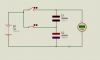
Mathematics is a wonderful tool to understand the complexity of the electrical behavior of a capacitor. The voltage across the capacitor is governed by V = Q/C where Q is the charge and C is the capacitance of the capacitor. The capacitor has not been charged. As a result, the charge on the capacitor is approximately equal to zero coulombs and by the definition of the voltage equation given above V = 0/C = 0. Hence, the voltage across the terminals of the capacitor is zero volts. The rest can be understood by applying Ohms Law (V = I *R). The internal resistance of a CAPACITOR can be modeled as a short when initially connected to a power source. I hope this assists you understand your question.