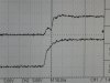
It worked! Removing the resistor, that is. Thanks, Ron.
The bottom tracing in the attachment is how it looks now.
I did not expect the emitter to go above the base without another factor. That factor was inductive kick from the welder. How it would get from the leads through the gate and back to the transitor, I don't know. It was just over caution. (Most of my experience has been with TIG, and the HF there goes everywhere, which obviously is not the situation here.) But, since the PCB is made, there is no problem leaving it off and adding later, if needed.
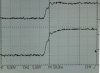
Stupid me, I calculated the potential base current
using a higher peak emitter current. I used the transistor rating (did I say dumb?), not the actual, realized it was getting close to the max for the 555, and threw the resistor in to limit it. Obviously, it limited it, and then I spent all of this time trying to avoid that limit without rethinking the original, wrong assumption. The peak emitter current should be a bit more than 500 mA as drawn (i.e., 12 V through 10 ohm). If I go to a 20 ohm gate resistor, then I will be back in the ballpark of 500 mA.
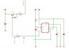
As for the resistor from the SCR gate to the cathode, the SCR I am using is not a sensitive gate one, if I read the datasheet correctly. It is an SKKT92. Do you think the resistor may still be needed?
The SCR will be in the cathode lead of the welder, based on the design link posted by Pommie a couple of weeks ago (
https://www.philpem.me.uk/elec/welder/). I don't anticipate going above 12V, but have made the prototype so that I could do that, if needed for the SS tubing I am trying to weld.
John