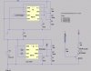
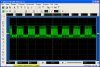
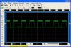
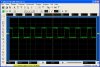
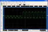
The LED frequency will be the same as the 555 output frequency. Use a CRO to view the waveform if you don't believe it. Or replace the LED with a resistor and measure the frequency at the collector (pointless, I know, but you can do it as an exercise).
It also looks like the carrier has to be switched on and off roughly 600us/600us (see page 2 of datasheet). This is sometimes done to weed out noise IR sources. You'll want another 555 to create this pulsing effect.
As to the centre frequency of the device: no idea. Sorry. You could find it yourself by decreasing the transmitter power to quite low (so you don't saturate the device - should give better readings) and sweeping the frequency - record the freq that the signal is detected, and the freq that it stops being detected at; the centre frequency should be in the centre of those 2 values.
")
 So, it looks like I will need to do 2 things to generate a suitable signal