i was asked whether paralleling 300 ohm antenna elements would yield a lower impedance. the short answer is it would raise the impedance. i wont go into as much detail as my original answer, but suffice it to say that a 300 ohm antenna element is made of two shorted 1/4l stubs, and a 50 or 75 ohm antenna element is made of two open 1/4l stubs, paralleling shorted stubs RAISES the impedance towards infinity, and paralleling open stubs LOWERS the impedance toward zero.
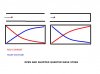
the first drawing shows how the voltage and current are seen on open and shorted quarter wave stubs.
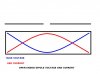
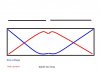
the second shows the voltage and current distribution on an open ended dipole. the fact that the current is high and the voltage is low at the feedpoint means LOW impedance.
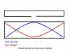
the third shows a folded dipole and the voltage and current distributions on it, the voltage is high, and the current low at the feedpoint, so this is a high impedance.
paralleling quarter wave stubs only makes them more efficient at what they do, so paralleling two open dipoles would bring the impedance closer to zero. paralleling folded dipoles would bring the impedance closer to infinity.
the first drawing shows how the voltage and current are seen on open and shorted quarter wave stubs.
the second shows the voltage and current distribution on an open ended dipole. the fact that the current is high and the voltage is low at the feedpoint means LOW impedance.
the third shows a folded dipole and the voltage and current distributions on it, the voltage is high, and the current low at the feedpoint, so this is a high impedance.
paralleling quarter wave stubs only makes them more efficient at what they do, so paralleling two open dipoles would bring the impedance closer to zero. paralleling folded dipoles would bring the impedance closer to infinity.