WOW !! You`re making a serious job out of it ! Beautifull !
Nice to have a lot of extra ideas about the circuit, so if something goes wrong,
well, wrong.... not doing as expected, I know where to look for the cause.
To clear some questions, although already explained: It is used for in a camper,
to charge the householdbattery from out of the starterbattery, while driving.
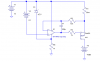
To keep the dissipation per FET low, I limited the current to some 5 or 6 Amps.
To get round 30 Amp as maximum current, I will use 5 or 6 of these circuits in parallel.
Maybe selectable, that when not a high current is needed, and in winter one need the
energy from the alternator more for driving, you can switch to only 1 currentsupply,
to get only 5 Amp chargingcurrent, just for buffering.
Besides that, these currentsupplys are (going to be) automatically switched off as soon
as the motor stops, and only allowed to switch on abt a minute after the motor is
running.
This also prevents returncurrent through the currentsupply.
To calculate the dissipation one should assume the output shorted !
Bcs it is POSSIBLE, that the 2nd battery is completely FLAT.
Won`t happen too often, but bcs it is possible, it should be taken in the calculations.
And, to make the heatsink not too big, there will be a fan, with thermoswitch mounted.
Oh, AND a heavy relay to switch both batteries parallel, when the differencevoltage
is < 0,5 Volt.
Kind regards,
Edwin
PS: I just got the idea, that, when the 2nd battery is fully charged and thus via the relay
is in parallel with the starterbattery, it will also get (a bit) discharged when the motor is
idling with all the lights on.... :-(
Yepp, a second alternator is always the best option !
aehhh.... when the relay is not yet activated.... there still will be returncurrent via the
currentsupply(s)


Back to the drawingboard ...


")

")