Hello all,
I remember, there was some problem when using opamps with their inputs near
the supplyvoltage.
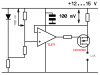
I now have a cirquit, I hope I can post that too, where the inputs are at +supply - 100mV.
Could I use any OP, or is there something to consider ?
The OPs should not be too expensive, bcs I need a lot.
Kind regards,
Edwin
I remember, there was some problem when using opamps with their inputs near
the supplyvoltage.
I now have a cirquit, I hope I can post that too, where the inputs are at +supply - 100mV.
Could I use any OP, or is there something to consider ?
The OPs should not be too expensive, bcs I need a lot.
Kind regards,
Edwin
") It is sometimes very confusing.
It is sometimes very confusing.