Electro Tech is an online community (with over 170,000 members) who enjoy talking about and building electronic circuits, projects and gadgets. To participate you need to register. Registration is free. Click here to register now.
Welcome to our site! Electro Tech is an online community (with over 170,000 members) who enjoy talking about and building electronic circuits, projects and gadgets. To participate you need to register. Registration is free. Click here to register now.
It is not a "voltage divider"; it is a "stabilized common emitter class A amplifier". For largest undistorted output swing, I would bias it so that V(c) =~V(cc)/2, but it is not very critical, since the drop across the emitter resistor will be a small fraction of V(cc) anyway.
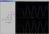
Here is a sim of a gain of 20 amp. The sim is run with different values of R3; where the lt. blue trace seems to have the lowest distortion (R3=90K).
Note the plot of V(c)-V(e). The lt blue (R3=90K) trace starts out at 5V (half V(cc)), so it looks like the textbook is right.
Did you doubt the text book? What did the text book say about the peak amplitude at V(c) before serious distortion appears there? Only someone who didn't care about distortion would operate this amplifier with an amplitude approaching these levels. At lower amplitudes, the bias point is less critical...
OK
another question: If I have two designs (like the above one) which
are the same except that one designed around IC=0.1 mA and the other has IC =10mA
I know that the first maintains the battery and has larger input impedance and larger output impedance than the second.
are there other differences between?
thanks
To show linearity a bit better, try using a triangle. If you dont mind doing a little more work, use a stepped wave with say 10 steps up and 10 down or more. Sines make it harder to judge.
OK
another question: If I have two designs (like the above one) which
are the same except that one designed around IC=0.1 mA and the other has IC =10mA
I know that the first maintains the battery and has larger input impedance and larger output impedance than the second.
are there other differences between?
thanks
I think it matters because samy555 has mentioned a current Ic=0.1mA.
For such small currents the condition RE>>1/g is not always fulfilled.
(1/g=Vt/Ic=26/0.1=260 Ohms).
If you have an amp that has good linearity and swing and scale all the resistances up, you get a little less gain but still good linearity and swing, but a little more swing if the transistor was operating in the higher saturation area. That's because the saturation voltage is less for less collector current.
The reason the amplifier has good linearity is because the forced gain is less than the circuit gain, and the emitter resistor provides for negative feedback. A smaller emitter resistor would result in larger swing, but not as good linearity.
Here's a shot of a transistor amplifier showing how good the linearity is. The upper trace is actually two traces:
1. The actual transistor output, and
2. A computer generated trace of a perfectly linear transistor amplifier with zero non linearity.
You cant tell the difference so well that's how good it is. Transistor is 2N4401.
Did you try setting the 'gain' to 10 instead of 20? Also, comparison using different values of collector resistor (and thus emitter resistor also and possibly bias) would be nice to see too.
The best view for the linearity is to see a 'perfect' triangle of the same amplitude very near to the actual output. That immediately shows any curve (non linearity) very clearly. I would imagine a careful hand could even draw a straight line right next to one or both sides of the output triangle, but an internal generated wave is probably better such as the scaled and offset input waveform itself.
The best view for the linearity is to see a 'perfect' triangle of the same amplitude very near to the actual output. That immediately shows any curve (non linearity) very clearly.
This site uses cookies to help personalise content, tailor your experience and to keep you logged in if you register.
By continuing to use this site, you are consenting to our use of cookies.