Continue to Site

Welcome to our site!

Electro Tech is an online community (with over 170,000 members) who enjoy talking about and building electronic circuits, projects and gadgets. To participate you need to register. Registration is free. Click here to register now.

  • Welcome to our site! Electro Tech is an online community (with over 170,000 members) who enjoy talking about and building electronic circuits, projects and gadgets. To participate you need to register. Registration is free. Click here to register now.

Where can I source these components?

Status
Not open for further replies.

Ted Bear

New Member
First off, Hello.
My name is Frank and I'm from Victoria down here in Australia. I'm into cars hence the reason for joining this forum. I do a fair bit of camping so enjoy setting up the LandRover for that purpose. However I'm working on a different project now and need some expert advice on a few thing from fuses to controllers to raise and lower a spoiler at preset speeds.

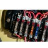
The first ling I'd like help to address is the changing of a fuse panel. Currently it uses the old ceramic fuses and the crimped end wires are held on each side by a screw block.
I'd like to change this to something that takes common blade type fuses.

After I take some pics I'll post them here.

TIA

Frank
 
Last edited:
Greetings Frank, welcome to ETO! I'm sure you will find lots of helpful people here eager to aid you in your projects :)

Best,
Matt
 
fuse.jpg
Thanks Matt. I thought I'd go straight to where all the expertise lives!!

Anyway, this is the fuse holder I'm thinking of putting in.

post.JPG

This is the post I need to have at each end of the fuse holder.

board.jpg

This is the old ceramic fuses I'm trying to replace.

My questions are:
What is the correct names for the fuse holder and the post thing?
And where is the best place to source these parts?

I know I will have to make a PCB to mount all these onto, but I think I'm up for that task.
Thanks in Advance
Frank
 
I know I will have to make a PCB to mount all these onto, but I think I'm up for that task.
I like your sense of adventure, that is good.

But, the first thing that jumped out at me was the screw terminal:
Screw terminal.png


When that is soldered in to a PCB and you tighten up the screw, the solder joint on the pin end will very likely break, or at best be weakened and eventually break due to vibration in the vehicle.

My next thought was that the whole thing would be rather exposed to the environment and look like a poorly engineered solution.
So a quick googling found this:
**broken link removed**

Fuse Box.png


A fully engineered solution for not much money.
(OK I know this is half a world away in the UK, but I am sure that similar things are available in Ozz.)

Reading the details, the wire connections to this fuse box are done with blade connectors, so you will have to crimp the appropriate connectors onto the existing wiring.
I think this may be a neater better engineered option that making a PCB etc etc.

JimB
 
G'day Jim,
Thanks for your thoughts and advice.
First off the existing fuse box does have a cover for it so any new fuse system will need to fit under it.
cover.jpg

Secondly the car is an old classic so I'm reluctant to cut the existing crimped ends off any of the wires.

There are two commercially available alternatives but their cost is prohibitive to say the least. Both around $520 AU less shipping.
I know one choice has a blown fuse LED but I don't need that.

You can see why I'm keen to make my own.

Cheers,

Frank
399.jpg
380.png
 

Attachments

  • 399.jpg
    399.jpg
    282.4 KB · Views: 209
OK, all understood.

There is a "Plan B" which I had in mind but didn't mention it because I thought the idea of bought in solution may be more attractive.

If the PCB for the fuse holders and terminals is made from double sided board, you can have copper pads on the top of the board and solder the body of the screw terminal to those pads.
Looking at the commercial example which you have shown, it looks as though the people who made that unit did exactly that.
If my interpretation of the picture is correct, there are copper pads under the terminals and some of them appear to be soldered.
Fuse Box 2.png


What do you think?

JimB
 
The terminal post in your picture is exactly what is in the normal tblocks I use
https://uk.rs-online.com/web/p/pcb-terminal-blocks/4948956/
when you remove the metal from the plastic it looks like the one in your picture .

The only thing is that they may be a tad too small to get the wiring in....

You say you are reluctant to change certain elements due to the cars "classic" status, but changing the fuse box is doing just that..

You can just buy a new ceramic one.
https://www.sheridanmarine.com/product/ceramic-fuse-boxes-with-8-amp-ceramic-fuses
 
OK, all understood.

There is a "Plan B" which I had in mind but didn't mention it because I thought the idea of bought in solution may be more attractive.

If the PCB for the fuse holders and terminals is made from double sided board, you can have copper pads on the top of the board and solder the body of the screw terminal to those pads.
Looking at the commercial example which you have shown, it looks as though the people who made that unit did exactly that.
If my interpretation of the picture is correct, there are copper pads under the terminals and some of them appear to be soldered.
View attachment 112003

What do you think?

JimB

Awesome Jim,

I would never have thought of that. That seems to be the solution.

Now all I need is a supplier??

Frank
 
You say you are reluctant to change certain elements due to the cars "classic" status, but changing the fuse box is doing just that..

Thanks for the links and the advice Ian,
I understand what you are saying but this way it can be returned to original with just a screw driver.

Cheers,
Frank
 
Frank
Can I suggest that we change the title of this thread to something a bit more meaningful than "Intro", the content has gone way beyond a simple introduction?

JimB
 
I don't know how that Range Rover passed quality control inspection, having exposed screw terminals that are easily compromised.
 
I don't know how that Range Rover passed quality control inspection, having exposed screw terminals that are easily compromised.
It did because it doesn't. (If you know what I mean).

Look back at post #5, there is a cover.

JimB
 
The older North American Chrysler Dynasty sedans and Mazda RX-7 sports cars used vacuum doors to operate the hidden headlights. Perhaps this idea could work with a spoiler, if those model cars or components were available in Australia.
 
Status
Not open for further replies.

Latest threads

New Articles From Microcontroller Tips

Back
Top