UnskilledOne
New Member
Hi, everyone. New poster here.
I'm aiming to build a high-voltage power supply for an electrostatic precipitator cheaply using a salvage flyback transformer. Fortunately for me, my in-laws had an old TV they wanted to discard. Unfortunately, I'm kinda puzzled by what I'm seeing.
The biggest puzzler for me is: What's that thing between the flyback and the suction cup?
Picture:
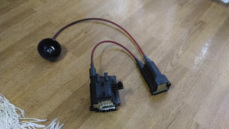
As you can see, it's got two high-voltage connections on the top (they're labeled "in" and "out") and 4 pins on the base.
My Google-Fu has failed me here: I'd think it was a splitter, but there's only one output. My next guess would be a rectifier/voltage multiplier, but aren't those supposed to be incorporated into the flyback casing? Anyway, I'm stumped.
Does anyone know what this thing is? Should I remove it from the line or keep it? If I keep it, what (if anything) to I do with the pins on the base?
-------
Second issue: I'm having trouble locating the pins for the primary winding.
Searching the internet has turned up conflicting explanations:
This flyback has 11 pins (not counting the pin for the "focus" and "screen" knobs). (Not sure if it matters, but pin 11 is shorter than the others.) I've measured the following:
(Note: Touching the probes on my multimeter to each other = fluctuates ~1.0-1.5 Ohm (I think this means my multimeter stinks...))
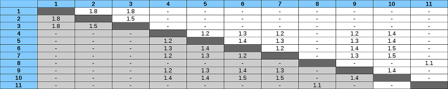
Any thoughts on which pair is the primary?
(The label is very faded, but I think it says "TFB4132BD." I haven't been able to find a pinout for this model online.)
-------
Third issue: What (if anything) should be done with the "focus" and "screen" knobs and their pin?
-------
Fourth issue: Thanks to the folks at Toshiba applying copious solder to both sides of the joints, I had to apply a lot of heat and violence to separate the flyback from the board. What are the odds that I've already fried this transformer? In general, how much abuse can these take, particularly in the form of a hot soldering iron against their pins?
-------
Thanks for taking the time to read this!
I'm aiming to build a high-voltage power supply for an electrostatic precipitator cheaply using a salvage flyback transformer. Fortunately for me, my in-laws had an old TV they wanted to discard. Unfortunately, I'm kinda puzzled by what I'm seeing.
The biggest puzzler for me is: What's that thing between the flyback and the suction cup?
Picture:
As you can see, it's got two high-voltage connections on the top (they're labeled "in" and "out") and 4 pins on the base.
My Google-Fu has failed me here: I'd think it was a splitter, but there's only one output. My next guess would be a rectifier/voltage multiplier, but aren't those supposed to be incorporated into the flyback casing? Anyway, I'm stumped.
Does anyone know what this thing is? Should I remove it from the line or keep it? If I keep it, what (if anything) to I do with the pins on the base?
-------
Second issue: I'm having trouble locating the pins for the primary winding.
Searching the internet has turned up conflicting explanations:
- The pair of pins with the highest resistance is the primary.
- The pair of pins with the lowest resistance is the primary.
- The pair of pins with ~1 Ohm resistance is the primary. (No explanation of which to choose if two pairs are ~1 Ohm...)
- The pair of pins with resistance ~0.5-2.0 Ohm is the primary. (Again, no explanation of which to choose if two pairs fall in that range.)
This flyback has 11 pins (not counting the pin for the "focus" and "screen" knobs). (Not sure if it matters, but pin 11 is shorter than the others.) I've measured the following:
(Note: Touching the probes on my multimeter to each other = fluctuates ~1.0-1.5 Ohm (I think this means my multimeter stinks...))
Any thoughts on which pair is the primary?
(The label is very faded, but I think it says "TFB4132BD." I haven't been able to find a pinout for this model online.)
-------
Third issue: What (if anything) should be done with the "focus" and "screen" knobs and their pin?
-------
Fourth issue: Thanks to the folks at Toshiba applying copious solder to both sides of the joints, I had to apply a lot of heat and violence to separate the flyback from the board. What are the odds that I've already fried this transformer? In general, how much abuse can these take, particularly in the form of a hot soldering iron against their pins?
-------
Thanks for taking the time to read this!
