Billy Mayo
Member
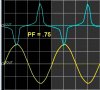
What is the difference between a product/unit with a power factor of 1 VS a product/unit with a power factor of .7?
Power factor of 1 is KV
Power factor of .7 is KVA
Power Factor of 1 means it's 100% Power/watts
Power Factor of .7 mean it's 70% power/watts and 30% the current and voltage is Power LOSS
Power Factor is the PEAK or RMS? Power factor is the True Power?
Power Factor of 1 is Voltage X current
Power Factor of .7 is Not Voltage X current, why is that?
")
