Continue to Site

Welcome to our site!

Electro Tech is an online community (with over 170,000 members) who enjoy talking about and building electronic circuits, projects and gadgets. To participate you need to register. Registration is free. Click here to register now.

  • Welcome to our site! Electro Tech is an online community (with over 170,000 members) who enjoy talking about and building electronic circuits, projects and gadgets. To participate you need to register. Registration is free. Click here to register now.

What voltage at the base emitter does a transistor conduct?

Status
Not open for further replies.
I haven't tried it but maybe some linear IC's work like this:
1) Connect the collector of the common emitter 1st transistor to the emitter of a common base 2nd transistor.
2) Maybe the collector current of the 2nd transistor will be linear with a linear voltage into the base of the 1st transistor. I think the distortion will cancel.

That would be a "cascode" configuration. Useful for a variety of purposes: as a high frequency, high input impedance RF amplifier, a single-ended mixer, and one way to increase negative feedbacl to improve linearity.
 

Attachments

  • cascode_205.gif
    cascode_205.gif
    3.3 KB · Views: 484
It's late, I don't want to do more maths since I just finished doing my daughter's income tax for the 2nd time in 2 days (she found more receipts today) and now I'm thinking that a cascode connected transistor pair doubles the distortion of only one transistor. :?
 
and now I'm thinking that a cascode connected transistor pair doubles the distortion of only one transistor.

Perhaps it does, and perhaps it doesn't. The usual applications I put this configuration to have always been RF apps, where tuned circuits and/or filters makes that irrelevant. However, **broken link removed** recommends this as a possible implementation, not specifically because it has a lower inherent distortion, but rather as a means to increase the negative feedback. Being able to increase that feedback improves linearity, and reduces distortion.
 
audioguru said:
It's late, I don't want to do more maths since I just finished doing my daughter's income tax for the 2nd time in 2 days (she found more receipts today) and now I'm thinking that a cascode connected transistor pair doubles the distortion of only one transistor. :?

It's commonly used in oscilloscopes and TV video output stages, the configuration gives good linearity, low distortion, wide frequency response, and a very high output swing.
 
Yeah, the bottom transistor in a cascode pair doesn't have any Miller influence since its collector isn't swinging up and down. The upper transistor also doesn't since its base is at AC ground. The result is a very wideband amp.

Now I see that the upper transistor doesn't have its non-linear transconductance multiplied like the lower transistor, therefore the total non-linearity is slightly more than a single transistor. :)
 
Hi,

0.6 to 0.7 is your diode drop across one of the pn junction of your transistor (Vbe). 1.4 to 1.6 will say that your Vbe is fully conducting at absolute temperature. Semiconductors have negative temp co, in which the lower the temperature, the higher its resistance (dynamic or whatever). With this it will tell you that it requires larger potential for electrons to cross between your n-material to your p-material.

hi,
This thread is over 3 years old.!!!:)
 
Not true. The collector current is an expotential function of the base - emitter voltage. The charge in the base - emitter region is proportional to the Vbe. If the charge is excessive, the transistor is in saturation. If not, it is in the active region.

Certainly Ic = hFE * Ib is a very useful relationship, Ib is required to maintain the b - e charge.

Len

The most useful relationship is as follows:

Ic = alpha*Ie.

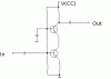
This is the relation we use to bias a bjt. Placing a voltage source across the b-e junction is never done. The device would be thermally unstable. The saturation current Ies in the Ebers Moll equation has a positive temperature coefficient.

Ie = Ies*exp((Vbe/Vt)-1).

Ies increases greatly with temperature. If constant voltage of 0.65V is connected b-e, a current is established per E-M. But temperature must increase due to power dissipation. Then, Ies increases, further increasing Ie, etc. Thermal runaway takes place.

Also, connecting a voltage source across b-e results in unpredictable emitter/collector current even not considering thermal runaway, since Ies varies widely with temp and speciman.

This is why we never "voltage-control" a bjt, nor an LED, nor any forward p-n junction.

To bias the b-e junction, Ib and Vbe are both needed. A constant voltage source, or a constant current source will provide both. With constant current drive, thermal stability is achieved. As temp increases, Ies goes up but Vbe goes down, resulting in a stable operating point. Vb = Vt*ln((Ie/Ies)+1).

We can control either the base current or the emitter current. If we establish Ib, then Ic = beta*Ib. This is thermally stable but suffers from "beta dependency". Ic can vary with beta which changes with temp, bias level, and speciman.

But if we control Ie, then Ib = alpha*Ie. Alpha is generally 0.98 to 0.998, or 0.99 plus/minus 0.01. This method is thermally stable and precise and predictable.

The bjt is usually controlled with emitter current, not Vbe, and usually not Ib. When used as a switch, Ib is often controlled. The device is overdriven in the base resulting in a forced beta smaller than the device minimum beta. This results in predictable operation.

Have I helped? BR.

Claude
 
Last edited:
Status
Not open for further replies.

Latest threads

New Articles From Microcontroller Tips

Back
Top