Continue to Site

Welcome to our site!

Electro Tech is an online community (with over 170,000 members) who enjoy talking about and building electronic circuits, projects and gadgets. To participate you need to register. Registration is free. Click here to register now.

  • Welcome to our site! Electro Tech is an online community (with over 170,000 members) who enjoy talking about and building electronic circuits, projects and gadgets. To participate you need to register. Registration is free. Click here to register now.

what to do next with zvs

Status
Not open for further replies.
I see, one issue is the current drawn from the variac when its o/p is 12v will be over 3 times what the 36v o/p is, would this overload the variac?, I suspect so.

Yes there are devices that will do that, one of the lm25xx monolithic simple switchers might do it though I think they top out at 30v, so you might have to use a switcher chip such as the staple diet TL494, or maybe sg3525.
 
ya, maybe i should learn to do proper power supply circuits, and speaking of, i took my middle size driver and put it on rectifier/ doubler from large zvs circuit and plugged in to variac, but even running at 12v,2A i am hearing a hum from variac, like there was when it ran at 10amps on another app, lots of smoothing capacitance too, should i be concerned? is there something idk on variac, does it math out like typical transformers?

Also I now have 3 drivers, one small pocket size one(no heat sinks), the medium, made with cpu fan, and large one(waiting on mosfets for final board) i am now using air core for inductor on 2nd.
 
Variacs like transformers can make a noise, because the operating frequency is so low the windings move around.
It would be a good idea to put an ammeter on your variac so you can constantly monitor the o/p current.
Variacs work in va the same as other transformers however there is usually a max current rating.

To an extent lots of smoothing capacitance increases the hum, well makes it more of a zzzz, because the capacitance draws spikes of current from the transformer whe the recitiders conduct.

Sounds like you are learning something about supplies, as you get better the pile of blown bits gets smaller, but never actually goes away.
 
sure hope so! that said pile is quit high, and in fact is specifically why i bought variac, so i can slowly ramp up on 120v circuits, so far my experience with supplies is merely utilizing existing ones.. especially my fav 12v5amp limited ciggy lighter emulator. i was hoping with variac i could ramp past that 12v, still the hum is louder than it should be(than usual), you are prolly right about the excess capacitance on rectifier, but im surprised that it would do that, why would it need to replenish more with higher caps, when there is only low draw from loads, i mean they shouldn't draw when they are already charged rite? and would only redraw to replenish the losses?

maybe im confused with variac, i presumed that it would be like other transformers where 120v@1amp=12v@10amp

also i worry how the +/-15v supply is going to fair when the variac is down at lower volts, will the driver be able to run at 2-5v, or maybe i should just run that power supply separate from the vairac while testing.?

anyway, my high power mosfets are finally here, an i got 3/4 of the circuits together, im starting now on the high power end of the board, but getting scared, already i wonder how the work coil attaches, i see the toroid that feeds it, but shouldnt the ends with the water feed be connected somehow, usually when i see a LC circuit its closed loop?

https://www.mindchallenger.com/inductionheater/overview.jpg
 
12v 5a limited cig lighter emulator, the fact that it is current limited also suggests that its also voltage regulated, so its not gonna go higher than 12v, or 13.8v if you increase the i/p, there will be a 12v reference, maybe a zener or 12v reg within the unit that fixes the o/p voltage.
Overvolting the i/p isnt good, the transformer core might saturate which could burn it and the variac out, also the smoothing caps will be overvolted and could also explode, literally.
Probably not gonna work too well reducing the i/p volatge either, the regulator circuit is still going to try and keep the o/p at 12v, when it goes below, noise, oscillations and other nasties may occur.
Sorry o be a killjoy.

If your +/- 15v supply is unregulated, it should be ok at less than 15v, and maybe just a little over if the voltage ratings of the caps and the transformer can take it. Cheaper transformers skimp on copper and iron core material so will go into saturation very soon over 120v, saturation causes the trans primary to appear as a short, which as you know isnt good, this might be the cause of the zzzzz.
Bigger supplies have bigger diodes and caps, larger caps take more to fill up so naturally in turn create more audible and electrical noise.

Yes i looked at the pic, the busbar looks as though its connected at one end, this is not gonna work, your right you need 2 connections, but if you look closer the one connection is a thin guage wire, so its probably a feedback, If you look at the heatsink, theres a yellow 6mm crimp connector on the back with a thicker black wire connected to it, i think there are 2 heavier wires comming off the back of the 'sink going underneath and connecting to the busbars where the caps are soldered.
Connect your work coil via 2 connections close up, you will probably go through a few work coils so make it easy to change them.
 
Last edited:
Is there Doctor in the house? No, but seriously looks fun doggy.

Here is a schematic of a plasma Globe; I traced the circuit and labeled the parts. They did use a CD4046 single driver config.


**broken link removed**

Good luck:)

kv
 
I just put together a supply to convert 12v to 200 - 650v, it uses nearly all salvaged parts, the main controller is a tl494, the trans is a philips tv supply transformer, the fets are 60n03's, not sure what they came from.
Its very possible to build a good switcher from salvaged parts, the biggest pitfall for me and others I've seen is understanding the properties of ferrite or iron cores.
 
nice kv, were you able to get that to drive with audio inputs?
it would be interesting to see what kind of response it would have with a frequency sweep.

yes p, i again fit that selection, as i understand the big thing hycurstics and saturation,
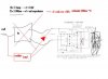
but he was very detailed in tutorial and i will be sure to follow that closely. about that test jig,
wasnt that what that was all about, i am about to get it together, but just wanted to be sure that it will work with these 74ls04 not gates.?

this assembly is going very slow , especially with the high end driver, slowly i am getting it all together,
i have never seen such big mosfets before, and have double checked and i think they are isolated where they clamp to the heat sink,but to be safe i put this thermal padding to isolate it all electrically, is this ok?
i also clamped and padded these huge diodes to the huge salvaged heat sinks aswell.

This is the padding im using to isolate everything....926-1114-ND
https://www.digikey.ca/product-search/en?KeyWords=926-1114-ND&WT.z_header=search_go
will this be ok?

In the +-15v supply i noticed we use those 1500uf/450v caps, which is the same as the high end smoothing, is so much capacitance actually required at the low end?

I also wonder what kind of heat will be coming out of the LM7815 and 7915, and what kind of sink i should use? initially, i was looking at the protection diode @3a so i assumed that was a safe rating and assume that circuit will be closer to 1amp, is this safe?


and one more question, not really related to zvs but with inductors, where im trying to do a small boost converter 1.5v - 4v 10ma max using the tl499, but i am having problem choosing inductor, first i tried this one:
811-2046-ND
https://www.digikey.ca/product-search/en?KeyWords= 811-2046-ND&WT.z_header=search_go
but that didn't seem to work, so i got one of these:
M8385-ND
https://www.digikey.ca/product-search/en/inductors-coils-chokes/fixed-inductors/196627?k=M8385-ND

which works fine,, but i can't help but feel that a 8$ toroid is overkill for such a small converter(?), any clue as to which one would be ideal?
 
Glasd to see your building a test jig, you can now make sure that your inductance can withstand the rail voltage for longer than it will in service.

That heat transfer material looks fine, manufacturers use stuff like that these days, so much less messy than the white cack.

Ref selecting inductors, the inductance is relavent, too high an inducatnce by order of 10x as mentioned probably will make the circuit inoperative, the current through the inductance will not have have the chance to build up to a high enough value to supply the load.
Generally the higher the o/p power of a switcher the lower the inductance, this means that the current will build up to a higher value before the switching tranny turns off.
A higher value inductance to an extent will decrease the rippl current through the inductor, but if its way too high the o/p voltage will drop as like I just mentioned there isnt enough time to store enough energy.

At 40kc with 1.5v input voltage at 50ma i/p current (taking into account of the boost from 1.5v to 4v at 10mA), I'd be looking at an inducatnce of 470uH, maybe 330uH.
A tl494 or tl496 will not run at 1.5v, you'll need a seperate supply, maybe you'd be better with a hartly oscilator aka joule thief.
 
i half hear that, im a start new post, i think:

https://www.electro-tech-online.com/threads/1v-boost-converter.142170/

so i seem to have OL the smaller driver somehow, so I'm going to be rebuilding it, however iv been thinking, by decreasing the capacitance current goes down, so maybe i could step volts up,

working with the old one i believe i used around 1uf eqivilant capacitance at 13v used 1.5 amps, (that was (20 parallel rows of (2 x 0.1uf caps in series)) so 20 watts, which was just enough to boil a small sauce dish of water, which is ideal.

by removing the caps it ran at about 100ma @13v,
so if i do that and then multiply the input voltage by 5, which brings me up to a rectified mains 60v, that would bring up my current to 500ma? and power to 30watts?

my problem is that a power supply for the original is costly and limited to 12v, plus all the extra space for the capacitor bank, with the new concept im eliminating complex supply(replacing with fuse, rectifier & cap) and extra work coil caps, but can add those caps as i go if i need more power,

with that im still close to ideal output, but do i need to think about wiring bases differently? and will this plan work?
 
Last edited:
Now thats a little confusing, the parallel capacitance will make the system resonate at a given frequency, your circuit being driven rather than self resonant means that at the right capacitance the current will be minimum (tank resonating at the driven freq), what you ought to do is find the capacitance the provides the lowest current, you can do this trial and error, or you can build a simple circuit that will make the tank resonate at low power and tweak it.
 
i think i did confuse,
im referring to driver in thread 13,
photo is what i want to do.. but i wonder if i need bigger resistors or diode clamps with that much more volts going to bases....
 

Attachments

  • photo1.JPG
    photo1.JPG
    34.7 KB · Views: 201
I see.
It just so happens that I have that same circuit connected up to a telly flyback trans here in my 'shop, and my bench supply goes to 60v.
I tried it, as soon as the supply got to 24v, the voltage of the zeners in my circuit current went straight to the limit point, I think both fets turned on. Initially it looks like the zeners need to be higher in voltage than the supply, that might be possible to do but you'd need to make sure the fets can withstand the zeners voltage rating on their gates, most can only take 20v or so accross gate source, at 60v supply 1k might be a better choice for the r's.
 
Status
Not open for further replies.

New Articles From Microcontroller Tips

Back
Top