Continue to Site

Welcome to our site!

Electro Tech is an online community (with over 170,000 members) who enjoy talking about and building electronic circuits, projects and gadgets. To participate you need to register. Registration is free. Click here to register now.

  • Welcome to our site! Electro Tech is an online community (with over 170,000 members) who enjoy talking about and building electronic circuits, projects and gadgets. To participate you need to register. Registration is free. Click here to register now.

what to do next with zvs

Status
Not open for further replies.

Dr_Doggy

Well-Known Member
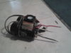
recently i pulled my zvs driver off the shelf, it is based on this model:
**broken link removed**
the only exception is that i put in 450v 40 amp mosfets, but is on the bench supply
12vdc, 7amps max, but i have variac along with doubler & rectifier circuit in waiting.
and want to add a relay to control supply power to L1, as i have found without it connected
the driver goes in to oscillation without the high current, which could come in handy.
i was wondering if i could clip a chip on the bases of the mosfets that would tell
me what my oscillation frequency is, maybe i can compare frequency shifts with core materials
would the toshiba74hc4060 ripple counter circuit be the rite path, or maybe there is something simpler,
like the opposite to a vco?

so first, in the original circuit it was rated for 12-36v,i am just wondering what my new
max voltage would be, mostly im concerned with my zener diodes(should i upgrade them too?)
more than current limitations, ie wires, supply,ect

second, the schematics i followed had this attachment to L1 for audio:
**broken link removed**
I wonder if i should stick to this path or switch up to the sg3535an used by KV here:
https://www.electro-tech-online.com/attachments/plasma-speaker-jpg.75710/

i initially used a 0.1mH inductor for L1, for now, but with the audio interface i wonder if i should go out and buy a transformer, or maybe wind one, and which values i should consider.

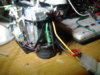
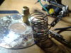
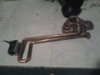
third, in the photos is my progress with my coils, the first one is the smallest, it idles at about 1.2amp draw from supply
(plus 0.5amp for cooling fan) and jumps up another amp when screwdriver is inside coil and heated past 100 degrees in just a few seconds, any smaller coils and the oscillation would break down, now with my final inductor which i am building now, as in the last photo, i am introducing a toroid to isolate the work coil,

i just wonder if i switch my secondary design to a small Tesla coil would the zvs tune in automatically, it is probabally smartest to switch up to a tesla coil, but i just wonder with the tuneing I will still need sparkgap and flyback but it will still sing rite? also I wonder since i will need to ground to AC outlet, what is a safe power limit?

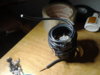
Now i seem to have a little problem, where i had initially used flyback transformer, but in doing so grounded the wrong pin causing a 15 amp surge and smoking the flyback, which is why i steped back to the zvs, to test the driver, plus i had several other flybacks on the shelf which seem to be dead aswell. i have even tried winding myown primary, lots of swing
on the bases, but no spark at the output, even before primary broke down. mean while the driver survived all of the surges and stayed cool though the whole thing, what would be a ez replacement to the flyback transformer?, since crt's arent seen at side of roads anymore..

but I also wonder what other cool attachments this driver could pump!?

simple answers pls! not too much need for detail, just direction!
 

Attachments

  • 20140213_152833.jpg
    20140213_152833.jpg
    695.3 KB · Views: 1,219
  • 20140213_152804.jpg
    20140213_152804.jpg
    832.2 KB · Views: 941
  • 20140213_152756.jpg
    20140213_152756.jpg
    708 KB · Views: 736
  • 20140214_113400.jpg
    20140214_113400.jpg
    715.3 KB · Views: 806
I like the copper layout, I bet you dont melt that.

The inductor is an important part of a zvs, without it zvs operation isnt possible (unless the supply lines are acting as one), an air cored coil is better as saturationwill not be an issue.

As far as tuning from the zvs to the tesla is concerned, the zvs shouldnt really interact with the tesla as the spark gap to an extent isolates the 2, when the voltage from the zvs is high enough the spark gap flashes over connecting hv to the parallel tesla primary and capacitance, taking the zvs out of circuit for a few uS or nS, the frequency of operation will depend more on the zvs's circuitry and the load the tesla assy puts on it.
 
yes, i forgot to mention for the induction heater, i started with this guy:
https://www.mindchallenger.com/inductionheater/
with a levitation coil

but i am taking small steps towards that since i want to learn more before doing the bigger driver, but i am still gearing up for it.

but about the second thing, i am wondering if i can take out the spark gap all together
i may be mistaken but i thought i saw SSTC's without spark gaps in them, (but maybe not)?

also PLS what is safe power output on a TC if i am not using an EARTH ground?
 
I'm not well up on tc's, zvs's no problem but I've never had an application for a tc.

You can drive a tesla without a spark gap if your using a square wave.
 
just wanted to be sure i read that properly,

but one more question, i dont get zener diodes, but rite now im running on 12v 2amp, 12v zeners, so ima step up the voltage until i get to 14 amps(my breaker size -1), the circuit is rated to go up to 36v, but i feel i will go past 36v, so i wonder, how to rate the zener diodes accordingly?
 
Not enough info.
Your zeners are doing what?, if they are protecting the gates of fets then they need to be a little below their max rating, you also i need to bear in mind the response time, but in this application thats probably not critical.
 
ok , i think about it and maybe i will just stick to its recommended voltages, next i think though ima do this driver:

https://www.mindchallenger.com/inductionheater/inductionlevitation4.html

but i just wonder what he is doing with the micro controller in there? is it a part of the pll switching, or is it more of just a moitor, i notice JP2 and JP3 in there suggests i dont need it...rite? ... but could use it for additional switching control?
 
As I read the schem it looks like the micro is acting as the frequency divider for the pll.
I first thought maybe it ensures resonance but theres no feedback, so it looks like just a divider and an led, maybe theres some sort of soft start as well.

The fet driver looks as though its had time spent designing it, be carefull with the fet drivers, they need decoupling well.
 
I am glad to hear that , i followed him since he had done several revisions and had some good results on YT, and left a-lot of details!
i will decouple, on the next page he put 330uf capacitors on pin 8 of the fet drivers. I think i should keep an eye on the micro controller though, when JP2 is used its just analog, so that must mean the filters on JP3 must mean voltage is controlled by smoothed PWM? ( or do you think i will need to send a specific pulse signal on pin PD7?)

wow i just tallied that circuit, totaling @300$!, hmm im also going to need to come up with a way to hold the work coil off the ground....
 
Had a closer look at home.
Control comes from either the pic or the 4046, the former when jp2 and jp3 are setup must use the atod input on the pic micro, so that an analogue voltage from the pot is converted into a frequency in sofware from the pic, so its a software control v to f.
The latter when jp2 and jp3 are configured is a true vco, the 4046 contains an analogue vco, v in f out.
Yes you can use the 4046 on its own without the pic.
As well as the 330uF use a quality 100nf in parallel, 330uF will have inherent series resistance reducing their effectiveness at hf's.
 
Last edited:
OK, i seen that and suspected that's what was happening, but Ty for mentioning that and confirming my suspicions, i will ensure to cap it up!

now since talking last i found another circuit for the same small driver, apparently its gauged for 500 watts, up to 40-60 volts.

rite now that small driver is running @12v 2-3amp , usually at about 40khz, but again its capable and heat sinked for 500 watts, but, i want another even smaller driver that fits the specs more comfortably and is more compact.
I am even thinking about bring the volts down to about 6 or 9v. (if its possible even)

So far i have tried to do two things, still working with 12v:
1) i tried to do a 555 timer astable circuit, then feed it to a 555 hex inverter (on the other side of a 556) to get my inversion, then feed each to the base of some small 9amp mosfets. but this didnt seem to work as there was too much current draw from source.
obviously a flaw in my design...

2)I have also tried to do another zvs driver but using this schematic instead:

but so far i cannot get it working, maybe though(prolly) a mistake with components on my end

so how should I go about downsizing? what components should i use for a smaller driver that will not go past 30 watts? it does not matter even if it is zvs, i am just interested in running a small,low power work coil.
 

Attachments

  • ADS00021.BMP
    219.4 KB · Views: 502
The circuit you linked us to should be fine for anything up to a few hundred watts, the thing limiting the power is voltage mainly, at 6v you will have a fairly low o/p.
The biggest cause for this kind of circuit either not to start or to pull too much current is the inductor in series with the + supply, if it cannot take a high enough dc current it'll saturate and electrically become like a piece of wire instead of a choke, are you sure the choke you are using can easily handle the dc current the circuit wants?

You probably could use a 555 as an inverter, but itdoesnt sound like a good idea, if you want a dual phase oscillator use a hex inverter chip like the 40106, use 1 gate as a osc and others as your inverter, parallel up 2 gates to drive the fets.

If you play with magnetics and you have a 'scope then I seriouly reccomend you build an inductor test jig, dead simple to make and tell you a lot about a choke or transfomer, I'll find a link to the one I built if you like.
 
i have LC meter if that s what you mean? but I could use something that could measure frequency for when im not attached to scope..

but thnx, i was going crazy troubleshooting, I was able to get a stable circuit just before some wires crossed and a pop... shot diode & fet, so now i need to wait :(, dont know why it wasnt working thou, but i did rediscover how to control current, by adjusting tank cap value:) (i always forget that's what they do!), so now i am more comfortable <2amps, which means finding a power brick will be easy.

lol, the L2 has been learning curve as well though, and guilty I am using inductor with core, my supply is 12@5amp regulated,7amp surge, i do notice it to be smoother running with the inductor, much better than my first inductor which i didn't realize wouldn't help with a high resistance! I havn't noticed too much with spikes on the supply so i wont worry too much, unless you again suggest otherwise, but will focus more attention when i do the bigger driver. L2 used is seen on driver under grey capacitors)

however now that you mention spikes i do see this noise at the beginning of my pulses at the collectors. I wonder if it is due to the way i soldered my capacitor leads, in the examples he suggested wiring caps at opposite ends to eliminate differentials form series resistances, but has left my design with this u shape copper?

And , i retried the smallest coil posted earlier and ran to a problem where i got some really high Mhz noise as seen in the last two photos. but idk where it comes from , the coil previously ran at 40khz. but now surges aswell, other coils work fine, maybe this one is just too small..?
 

Attachments

  • ADS00018.BMP
    219.4 KB · Views: 480
  • 20140321_020337.jpg
    20140321_020337.jpg
    874.7 KB · Views: 557
  • ADS00029.BMP
    219.4 KB · Views: 473
  • ADS00030.BMP
    219.4 KB · Views: 479
Nope not lc, a test jig applies a squarewave to a coil under test, using a power supply, you can vary the pwm using a pot and the voltage from the supply, the idea is to find out when the inductor will saturate both current and time wise, and show you the saturation curve, you can also measure the inductance.

L2 the inductor in series with the supply is important, not just to stop noise from getting back to the supply, it also enables the circuit to run resonant, without it the circuit will pull loads of current and the trans primary would probably saturate.

Hf noise, in the order of mhz can be a few things, the most likely being the capacitance of the fet and stray inductance in the wiring to the primary, these will ring together and generate hf, making the wiring as short as poss will reduce this, you could also fit a rc snubber across the fet drain source to damp this out.
 
ok, lets see jig, i will give it a try,
will it be ok if i add the new inductor in series to the old one, then it would stack up like our caps did earlier rite.
yes,wiring to the primary, those were the wires he twisted to stabilize, im still suspicious of coil , but will snub if it comes down to it.
 
This is the one I use, it uses a hex inverter chip, theres another on the net that uses a couple of 555's.
You dont need the sync output if your 'scope is digital, if its analogue then you need it, my analogue 'scope take a bit of fiddling to get a good trace.
Scroll down towards the end of the page:

https://www.dos4ever.com/flyback/flyback.html

Wiring inductors in series isnt a good idea, if you must then position one 90 degrees to the other so they do not couple to each other, its unpredictable what will happen when you series chokes, unlike other components the magnetic field produced has an effect on other chokes.

P.S. I put the sense resistor in the drain leg of the fet (so the 'scope ground was test bench ground) as I had trouble getting the 'scope to trigger with the sense resistor in the + line.
 
yah, i will prolly have problem too, as my scope is from ebay(china) and i have gotten the single trace to work, but its not proper, i forget but i think i have to zoom volts super far down so my lines go off the screen, then zoom out after the trace.

q's about test circuit:
you say i can just use hex inverters? but those others are Schmidt triggers? and is N1 non-inverting? and what is feeding it power, does it feed back from other N's, from gate? what can i use for t1?


also looking at the dos page reminded me of a circuit im trying to do, where since i have the variac that outputs 12-120vac, is there like a smart buck/boost converter i can do where it will regulate the 36v so i can eliminate the second rectifier and transformer? I am almost thinking about switching to battery s just to eliminate 2nd 120*v feeds
 
Last edited:
Some ebay digital 'scopes are not that good, some are, whats the min volts/div on yours then.

A schmitt trigger is just a version of hex inverter, you can get schmitt nand gates and others, but yes they are still hex inverters, schmitt means they are meant for analogue signals, hex just means there are 6 of them in the chip.
Yes the chip needs power, gnd on pin 7 and + on pin 14, you can run cmos from 3v to 15v, probably a good idea to put a 100nf close to the power pins of the chip.
I think ron the author probably forgot to put the inverter circle on N1, they are all inverters.

My T1 orginally was a IRF540, but I blew that, now its just the first N channel I pulled out of my scrap box.

Not sure about the buck/boost, do you actually mean buck/boost as in a circuit that can increase and decrease voltage?, I think the best approach to that would be to put a transformer on the o/p of the variac so you get 0 -120v from the variac, and 0-36v from the trans, if I understodd what you meant that is.
 
you get it, but the thing is that when variac is 12v min, so trans out would be 3.3v , but that would then under power the +15 & -15 regulators controlling the op-amp,

so is there a way to do a smart boost converter so it boosts what i need , only when i need it?
thinking about it , hows this, i would put the boost converter on output of trans after rectifier and like a VCO to feed boost conv, so it would tune boost via vin.. but would stop working at high freq when volts were sufficent?
 
Last edited:
Status
Not open for further replies.

New Articles From Microcontroller Tips

Back
Top