RODALCO
Well-Known Member
The toggle switch option is an excellent idea.
PSU size, depends upon the total maximum load. If on average 250 mA is drawn, look for a 24V 500mA supply.
Best is to build one yourself with a transformer, bridge rectifier , good size capacitor 10000uf 63 Volts and fused in- and outputs.
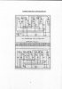
The slaves on this board are the ones with the alternating polarity inputs?
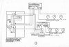
They may need connecting to P and N terminals as those clocks require +24V-0 , -24V-0, +24V-0, -24V-0 and so on.
BTW did you put a series resistor on your test led's ? ( about 2k2 or 2k7).
Regards, Raymond
PSU size, depends upon the total maximum load. If on average 250 mA is drawn, look for a 24V 500mA supply.
Best is to build one yourself with a transformer, bridge rectifier , good size capacitor 10000uf 63 Volts and fused in- and outputs.
The slaves on this board are the ones with the alternating polarity inputs?
They may need connecting to P and N terminals as those clocks require +24V-0 , -24V-0, +24V-0, -24V-0 and so on.
BTW did you put a series resistor on your test led's ? ( about 2k2 or 2k7).
Regards, Raymond