Continue to Site

Welcome to our site!

Electro Tech is an online community (with over 170,000 members) who enjoy talking about and building electronic circuits, projects and gadgets. To participate you need to register. Registration is free. Click here to register now.

  • Welcome to our site! Electro Tech is an online community (with over 170,000 members) who enjoy talking about and building electronic circuits, projects and gadgets. To participate you need to register. Registration is free. Click here to register now.

What size Potentiometer?

Status
Not open for further replies.
Hi

Looking for theoretical advice on how to choose the right size potentiometer for a project.

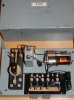
I have a master clock that runs 3 external slaves and it's internal slave and normally if I were adding extra slaves to the the series circuit I would up the supply voltage by 1v per 3ohm coil on each slave and just keep adding on where required.

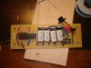
Now I want to add a relay box into the circuit where the relays within box are also in series with the slaves.This relay box will have it's own power supply for the external devices going to say 4 relays and I need some form of control to the amount of supply going to the external devices the relays are switching. I'm thinking of using Potentiometers for that purpose but I'm not sure about the size required. I will need to adjust between say 3 and 20+v. Normally within my master are old rheostats but I'm not sure about picking these up these days.


Any advice on the potentiometers size and other methods will be great.

Regards
 
Mark,

what, exactly, is any given potentiometer powering? Your description is hard to follow. Can you supply a diagram?
 
Still need a better explanation of what you are trying to do. What is the volage and current to these "slaves"? Is that AC or DC?
 
Mark,

what, exactly, is any given potentiometer powering? Your description is hard to follow. Can you supply a diagram?


Hi Mike

Unfortunately not got a diagram yet.

The devices being controlled from the relay aren't yet decided what I do know is that each device will require a supply from 3-20 or should I say 20-3 ish volts so I need to adjust for that range.
The info I'm really looking for is how to calculate the size of the POT. required (see maplins link) My max supply to the POT. will be max 20v.

**broken link removed**

Is this enough info?
 
Last edited:
Still need a better explanation of what you are trying to do. What is the volage and current to these "slaves"? Is that AC or DC?


Hi

The supply is DC. The slaves won't be on the same circuit as the external devices but the coil on the relay will be.That way I can connect anything up to the relay between 3 and 20 volts.
Each slave are around 4ohms.

I'm ok with the coils in the series circuit as they will be all controlled every 30 sec from the master.They will be all around the same including the coils on the relay so to switch all those it's a case of upping the supply 1v per 3ohm coil. It's the supply range for the external devices that are switched from the relays that's in question, these have their own supply that I need to adjust between 20 down to 3v.

I'm sure that the external devices will be DC. 500ma. ish.

Hope this explains!!

Cheers!!
 
Last edited:
Hi
It might be that a POT. of any size is not the practical solution to control the supply but seeing as the external devices would be max 500ma. I thought they would do.Like I said in most cases in master clock old style rheostats are used and I need easy manipulation.
 
Hi
It might be that a POT. of any size is not the practical solution to control the supply but seeing as the external devices would be max 500ma. I thought they would do.Like I said in most cases in master clock old style rheostats are used and I need easy manipulation.

hi Mark,
What is the resistance of these external devices.?
 
Hi Eric

Sory late to reply just doing the Dad's taxi run!!

Each of the relays will have slaves connected to it, the amount unknown.Each coil on each slave will be around 3-5ohms averagely around 4. I may have one on then again I might have ten on so that's 3-50 ohms max.

Another relay will have just one solenoid on at around 50ohm.

I probably will have three relays in total and like I said the coils in the relays will be in series with the master slave so switching every 30 sec. Because the amount of slave going on each relay is unknown I require adjustment down from around 20v to 3v so I can add on and take off a slave at will and then adjust the supply accordingly!!

Does this make sense?? or should I say am I !!

Regards
 
Last edited:
potentio meter

As most slave clock coils are around 3 to 4 ohms. The easiest option is to make up a string of 3.3 or 3.9 ohm, 5 Watt wire wound resistors in series with the slave dial circuit.
In the case that you remove a slave dial add an extra resistor in series in the case that you use a 20 Volts dc supply.
You can leave the R string in series permanently and short or unshort a resistor out to suit the series circuit.

Try to source a 60 or 100 ohms 5 or 10 Watt wire wound pot meter which gives you the complete ohms range,
A second hand shop of old electronic gear may have them with a bit of luck.
or

e.g 3 slave dials at 250 mA ( 4 ohms ea) and on 20 Volts dc require a series R of 80 ohms minus 12 = 68 ohms.
You could make a string of 20 x 3.3 ohms resistors ( makes 66 ohms)

or fit two 3.3 ohm resistros and one 47 ohms or 56 ohms R (5Watt) to allowe you to add one or two extra slaves if required, less messy wiring.

or probably better to opt for a lower voltage, say 12 Volts.

I run a Gents master of 12 Volts with one slave dial ( 4 ohms ) and a series R of 39 ohms, about 270 mA and seems to work perfectly with no missing clock pulses.
 
Hi Eric

Each of the relays will have slaves connected to it, the amount unknown.Each coil on each slave will be around 3-5ohms averagely around 4. I may have one on then again I might have ten on so that's 3-50 ohms max.

Another relay will have just one solenoid on at around 50ohm.

I probably will have three relays in total and like I said the coils in the relays will be in series with the master slave so switching every 30 sec. Because the amount of slave going on each relay is unknown I require adjustment down from around 20v to 3v so I can add on and take off a slave at will and then adjust the supply accordingly!!
Regards

hi Mark,
The reason I asked for the resistance of the coils is so that not only the resistance value of a required resistor can be calculated but also the wattage rating of the resistor.

The link you posted shows a low wattage potentiometer which would most likely burn out at 500mA.

The advice that 'Rodalco' has posted is the best way to solve the voltage drop problem.
 
Last edited:
As most slave clock coils are around 3 to 4 ohms. The easiest option is to make up a string of 3.3 or 3.9 ohm, 5 Watt wire wound resistors in series with the slave dial circuit.
In the case that you remove a slave dial add an extra resistor in series in the case that you use a 20 Volts dc supply.
You can leave the R string in series permanently and short or unshort a resistor out to suit the series circuit.

Try to source a 60 or 100 ohms 5 or 10 Watt wire wound pot meter which gives you the complete ohms range,
A second hand shop of old electronic gear may have them with a bit of luck.
or

e.g 3 slave dials at 250 mA ( 4 ohms ea) and on 20 Volts dc require a series R of 80 ohms minus 12 = 68 ohms.
You could make a string of 20 x 3.3 ohms resistors ( makes 66 ohms)

or fit two 3.3 ohm resistros and one 47 ohms or 56 ohms R (5Watt) to allowe you to add one or two extra slaves if required, less messy wiring.

or probably better to opt for a lower voltage, say 12 Volts.

I run a Gents master of 12 Volts with one slave dial ( 4 ohms ) and a series R of 39 ohms, about 270 mA and seems to work perfectly with no missing clock pulses.


Hi Ray

Wow!!! your ending quote is right 'there are more ways to Rome'

Sounds a a feasible solution but would I have to make the coils myself, the bobbin as well?
I like the thought of a small box full of these wire wound resistors, all can be connected up to terminals for easy removal. Trouble is making them!!! advice will be needed there also!!

All I wanted to do is sort of replicate a Gent relay box 'see photo' these are 24 supply 250ma but with a variable rheostat for adding and taking away slaves do this x 3.

On another note interestingly I have a 50ohm coil I want to power but not sure how many Volts it requires, is there a calculation for that or is a trial and error??? I have tested and it will operate at 6v 250ma.

Edit:

Ooooop!! is this the type you mean? thought I was going to have to make some!!!
**broken link removed**


Regards
 
Last edited:
Hi

The Gent Relay box!!

So would I be ok to run the 3 strings of resistors and the slaves from one 20v psu.max 250ma?
See I need the three lines to keep things easy and separate as not all connected are slave clocks.

1 string of slaves
1 string with the 1 50ohm solenoid
1 string spare!!

Regards
 

Attachments

  • n_aCAYLQ492.jpg
    n_aCAYLQ492.jpg
    32 KB · Views: 182
Last edited:
The Maplin R's are 3 Watts ideally you should get 5 Watt R's

They look like a rectangular white ceramic ( I see if i can find a web photo or i make one for you )

Nice relay box, have never seen one of these before.

The basic ohms law formula is U = I * R
where
U is Volts
I is current ( in Amps)
R is ohms

In your case the 50 Ohms value of the coil is fixed, by adding extra resistors you can change that value to adapt it for a different voltage

For your 50 ohm coil, and you need 250 mA current,
U = 0.25 * 50 is 12.5 Volts

To run this coil at 24 Volts and keep the current at 250 mA, therefore 24/0.25 = 96 ohm total value required.
Coil is 50 ohms so a series R of 46 ohms need to be put in series. Get a 47 R 5W resistor ( E12 series)

You could put two of these 50 ohm coils in series at 24 Volts at a current of 240 mA.
 
Last edited:
The ceramic 5 Watt resistor looks like this.
 

Attachments

  • 5 Watt resistor.jpg
    5 Watt resistor.jpg
    19.7 KB · Views: 188
  • 5 Watt R-s on a cct board.jpeg
    5 Watt R-s on a cct board.jpeg
    597.3 KB · Views: 198
Hi Ray
Gent Relay box is quite std equipment but mainly used in a changeover circuit.My seconds Gent master ought to have one for the slaves to operate from their own supply but me being me and like most other I adapted a gpo. 3000 relays and it works a treat.

Cheers for the info it's a lot clearer now.

When you say 'short out' a 3,3 ohm resistor when adding extra slaves do you mean by adding a jumper wire across it? Thinking of a more professional looking method.

Advice on purchasing or making a suitable Psu required for for all three circuits assuming they are all full which they will be whether it be with resistors or slaves!! don't want to be burning out a psu.OR WORSE!!!!!

Kind regards. most appreciated!!!
 
Last edited:
hi Mark,
The reason I asked for the resistance of the coils is so that not only the resistance value of a required resistor can be calculated but also the wattage rating of the resistor.

The link you posted shows a low wattage potentiometer which would most likely burn out at 500mA.

The advice that 'Rodalco' has posted is the best way to solve the voltage drop problem.

Eric

Much Appreciated!!!

Regards
 
I like to have a good safety margin in the resistors so they don't get too hot in case of a fault.

A 7 or 10 Watter would be even better but they are a lot bigger and more expensive.

The 5 Watt R's are relatively cheap and easy to get from any electronics place.
 
I like to have a good safety margin in the resistors so they don't get too hot in case of a fault.

A 7 or 10 Watter would be even better but they are a lot bigger and more expensive.

The 5 Watt R's are relatively cheap and easy to get from any electronics place.

Hi Ray

Nough said!!!

I'm thinking it might be a advantage if I added toggle switches on each resistor just to make it easy to short them..

What size PSU. should I buy? again being safety conscious!!

This conversation leads me back to my Panels and the power required to run them..I'm told that they run off 24v dc. for the entire board. I've taken out and tested each transistor circuit and they work fine. I added 24v to it and then LED's to the P & N (outputs) and the shorted (4) and the LED's alternated ok.I did this on each of the 5 circuits and all were fine.

But I'm suspect that the entire board runs on 24v as a group test I get no response from the panel slaves!!!! What I do know is that (4) will have -24v to it because that's all my master puts out!!

It confused me and without advice I'm not going to put any more V's in.

Cheers
 
Status
Not open for further replies.

Latest threads

New Articles From Microcontroller Tips

Back
Top