Continue to Site

Welcome to our site!

Electro Tech is an online community (with over 170,000 members) who enjoy talking about and building electronic circuits, projects and gadgets. To participate you need to register. Registration is free. Click here to register now.

  • Welcome to our site! Electro Tech is an online community (with over 170,000 members) who enjoy talking about and building electronic circuits, projects and gadgets. To participate you need to register. Registration is free. Click here to register now.

What part can I replace it with?

Status
Not open for further replies.

Abraham90

New Member
Hello,

Trying to troubleshoot a defect Sonos Sub since it doesn’t start.
I have started some measurements and I have observed the following which might sound strange.

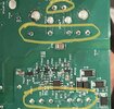
The Bridge Rectifer, when measuring between negative and positive is showing around 0.56V while I expected around 0.9V since two diodes are in series. Does it mean it is defect? When measuring between other combinations on the bridge rectifier, it seems to be fully working with regard to voltage drop and resistance except for the 0.9V.

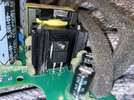
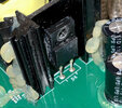
However, there is another part that caught my attention. I have measured this part (shown in the picture) and it seems to be defect. When I do diode measurement, I am getting 0.0V in both directions and ohm measurement of 0.2 ohm in both directions as well (suspected short). It seems to be connected to the transformer just behind it. But I cannot find a replacement for this as there is no marking on it. Maybe it’s a difficult question, but how do I proceed after this? Thank you.
 

Attachments

  • 04F80A5A-6FC0-4D83-9624-78B9B84411C8.jpeg
    04F80A5A-6FC0-4D83-9624-78B9B84411C8.jpeg
    4.3 MB · Views: 227
  • 26F25CE7-E7D4-46CB-A372-73A6C57731DF.jpeg
    26F25CE7-E7D4-46CB-A372-73A6C57731DF.jpeg
    751 KB · Views: 245
If you're testing them in-circuit, then don't - you're not testing just the diode/bridge, you're also testing everything else connected to it.

BTW, randomly testing components isn't the way to fault find.

In a switch-mode PSU though, it is useful in a small number of areas - one of which is the secondary rectifiers - these quite often go S/C. Assuming D6 is a secondary rectifier?, then it could well be S/C - once you've found a secondary rectifier that reads S/C you need to take it out, and test it again, to confirm it's the diode, and not something else.

Generally, when testing the secondary rectifiers, I wouldn't use both probes across the diode - I'd stick one probe on chassis, and simply run the other probe down the positives of the rectifiers - as the negatives of the rectifiers go to chassis via the transformer windings. If one reads short, I'd then stick the probe on the negative side, just to check in case it's a negative supply rail :D This only takes seconds, as it's all easily accessible and obvious.
 
Hello,
Thank you for your response.

I know testing components randomly is not the way to go but I have been trying to follow the path from input voltage all the way to the transformer and beyond.

I have de-soldered the part and it still gives a short circuit reading and 0.0V reading. So I assume that the transformer is receiving a badly regulated voltage. (The input pin seem connected to the transformer and the output goes to the transformer as well when checking the PCB board?). I have marked the two pins and the transformer connections (with the many pins).

Next question is what I should replace it with since there is no marking on it… could it be a schottky diode? Why would the manufacturer not put marking stamp on the part? Seems so counterproductive.
 

Attachments

  • 2D96EFF9-B8C0-4B09-879C-B0A6888A9CCA.jpeg
    2D96EFF9-B8C0-4B09-879C-B0A6888A9CCA.jpeg
    237.1 KB · Views: 232
I can also mention that everything seems to work fine until we reach the transformer part. There is an input of 315V, which I assume is probably because of the RMS of 230V after the transistor located before the transformer. However, there is no output from the transformer and there is a faint pip sound coming when it attempts to switch on Since there is a failure somewhere; it seems to shut down. I assume because of the short circuit in the second rectifier, the feedback mechanism makes it shut down. Is that a correct assumption?
 
I can also mention that everything seems to work fine until we reach the transformer part. There is an input of 315V, which I assume is probably because of the RMS of 230V after the transistor located before the transformer. However, there is no output from the transformer and there is a faint pip sound coming when it attempts to switch on Since there is a failure somewhere; it seems to shut down. I assume because of the short circuit in the second rectifier, the feedback mechanism makes it shut down. Is that a correct assumption?
Yes, the PSU will immediately shut down because of the short - if you're lucky (if not it will destroy itself) - it's not the feedback though (which is voltage regulation), it's over current protection.
 
Alright. Then I might be on to something here.

Just out of curiosity, why is the secondary rectifier diode connected back to one of the transformer pins? I am reading the circuit board correct?
 
Hello,
Thank you for your response.

I know testing components randomly is not the way to go but I have been trying to follow the path from input voltage all the way to the transformer and beyond.

I have de-soldered the part and it still gives a short circuit reading and 0.0V reading. So I assume that the transformer is receiving a badly regulated voltage. (The input pin seem connected to the transformer and the output goes to the transformer as well when checking the PCB board?). I have marked the two pins and the transformer connections (with the many pins).

Next question is what I should replace it with since there is no marking on it… could it be a schottky diode? Why would the manufacturer not put marking stamp on the part? Seems so counterproductive.

Common practice, particularly on cheap Chinese gear, but even on decades old equipment manufactured in the West.

The actual 'part' doesn't matter, and a wide range of parts are interchangeable in that position - so as to avoid confusion the manufacturers often use 'in-house' numbers, and have the semiconductors supplied with that (meaningless) number printed on it. So you order your components from various different manufacturers, giving a required specification, and telling them what you want printing on them - so if one manufacturer isn't able to provide them, you can get them elsewhere. Basically they simply choose a suitable existing device from their range, and print it accordingly.

It will be a schottky diode diode, 100% - just choose one the same shape, with the connections the same way round - anything that sort of shape should be a similar current, and a couple of hundred volts rating should cover it.

For all my schottky diode repair needs I used to keep just two types - in draws labelled 'big diodes' and 'small diodes' - essentially the same size/shape as 1N5408's and 1N4001's. Those two replaced pretty well everything I even came across. The type you've got is somewhat rarer, and I'd order something suitable if and when I needed them.
 
Alright. Then I might be on to something here.

Just out of curiosity, why is the secondary rectifier diode connected back to one of the transformer pins? I am reading the circuit board correct?
It's the feed to the diode from the transformer.

If you look at this circuit, there are five rectifiers at the left, D12-16, connected to transformer windings down to chassis - this is similar to what you've got:

 
Hello,
Thank you for your response.

I know testing components randomly is not the way to go but I have been trying to follow the path from input voltage all the way to the transformer and beyond.

I have de-soldered the part and it still gives a short circuit reading and 0.0V reading. So I assume that the transformer is receiving a badly regulated voltage.
Oh, no; the rectifier short means AC is getting to all the circuitry downstream (which was
designed for DC operation). Sometimes replacing the rectifier is only the start of troubleshooting
(a filter capacitor shorted will sometimes cause this kind of rectifier fault).
This kind of shorted diode usually happens on the high-current low voltage side, so
the transformer OUTPUT connects to it, not the input. Bad voltage into the
transformer would saturate the transformer and burn a fuse, not an output rectifier.

I'd judge from the heatsink that this is a circa 8A fast-recovery diode, in insulated 'fullpack'
form, TO-220; something like <https://www.digikey.com/en/products/detail/micro-commercial-co/MURS860FA-BP/12395916> perhaps. Best, though, to try to find a schematic or
maybe even clean the removed component and examine with a microscope to find
a part number.
 
Oh, no; the rectifier short means AC is getting to all the circuitry downstream (which was
designed for DC operation).

I'm sorry, but you're posting complete and utter nonsense - that is 100% totally untrue.

If you don't know anything about servicing (or electronics) why post incorrect advice in a forum? - the reasons are very simple and basic.
 
Oh, no; the rectifier short means AC is getting to all the circuitry downstream (which was
designed for DC operation).
the filter cap shorts out whatever little bit of AC that gets through during the startup chirp, and the excessive current then immediately shuts down the power supply, so nothing downstream takes a hit.
 
It's the feed to the diode from the transformer.

If you look at this circuit, there are five rectifiers at the left, D12-16, connected to transformer windings down to chassis - this is similar to what you've got:

Hi,

thanks once again.
Do you think this would work or is it rated too low?


I am having troubles finding something that is better rated than this one and is fully insulated like mine (fullpack variant)… looks similar with a “broken” off pin in the middle just like the one I found in the link above.

I must be honest with you that this is actually the first time I am attempting to repair a circuit board … ☺️
 
As long as the connections are the same way round it should be fine.
Seems like I found another one that has a higher voltage rating.


Should work fine too?
 
Seems like I found another one that has a higher voltage rating.


Should work fine too?
Yes, but probably no need for that voltage - on the assumption it's a secondary rectifier.
 
Yes, but probably no need for that voltage - on the assumption it's a secondary rectifier.

Your feedback has been very valuable for me. I thank you a lot. I will post here once I have soldered the part so you know what came out of this repair.
Have a great weekend sir.
 
the filter cap shorts out whatever little bit of AC that gets through during the startup chirp, and the excessive current then immediately shuts down the power supply, so nothing downstream takes a hit.
Or, the original fault was a short in the filter capacitor, which caused the rectifier to fail shorted... and the power supply shuts down to prevent fire, but not necessarily to protect other functioning parts. There's a likely scenario that when the shorted diode is replaced, other faults will be uncovered.

It's sometimes called 'zipper mode' of failure.

Sorry, but you're talking absolute crap again - you've obviously never been involved in electronics repair - so why post rubbish about it?.

Secondary rectifier failure is EXTREMELY common, it doesn't cause other damage on the secondary side, and it's not caused by a failing capacitor.

The only issue is that it 'might' cause the primary side to 'self destruct', but this would be very, very rare - as the over current protection stops the PSU getting as far as running properly (often with an audible chirp).
 
Secondary rectifier failure is EXTREMELY common, it doesn't cause other damage on the secondary side, and it's not caused by a failing capacitor.
That can't be right; secondary rectifier failure is due to overheating, and excess downstream
currents, such as caused by a filter capacitor short, are certainly a possible cause.
Overheated semiconductors re-diffuse, and that almost always makes short-circuit failures,
such as second-breakdown in power transistors.
 
One of the commonest causes of semiconductor failure is thermal cycling.
That is due to differences in expansion between the semiconductor wafer, it's connecting leads, the encapsulant, and possibly with the PCB adding to the stresses, depending on the package type and mounting.

Another is the repeated short-term overloads at switch-on, if the components are not rated adequately to allow for the brief current spikes as other parts charge up to their operating voltages; again, a thermal shock effect.

Neither needs an external fault condition to cause the failure.
 
Status
Not open for further replies.

Latest threads

New Articles From Microcontroller Tips

Back
Top