Continue to Site

Welcome to our site!

Electro Tech is an online community (with over 170,000 members) who enjoy talking about and building electronic circuits, projects and gadgets. To participate you need to register. Registration is free. Click here to register now.

  • Welcome to our site! Electro Tech is an online community (with over 170,000 members) who enjoy talking about and building electronic circuits, projects and gadgets. To participate you need to register. Registration is free. Click here to register now.

What is the cut off frequency of this LC and RC combination?

Status
Not open for further replies.

I think that the problem is in Wolfram Alpha with complex numbers.
I tried simple transfer function 1/(1+1/iw) and it can't find solution for w at 0.707
If you assist by writing the denominator as sqrt(1+1/w^2) it finds the solution.
 
To the OP. If you're going to be doing this sort of thing a lot, you would be well advised to get some software that you can run on your own computer rather than trying to do things with a web based software like Wolfram Alpha.

I recommend Maxima which is free:

http://maxima.sourceforge.net/

I think it can do all the things you need to do.
 
I think that the problem is in Wolfram Alpha with complex numbers.
I tried simple transfer function 1/(1+1/iw) and it can't find solution for w at 0.707
If you assist by writing the denominator as sqrt(1+1/w^2) it finds the solution.

The procedure you describe can be done with the OP's transfer function but it involves a lot of algebra.

separate-png.74204


The OP could try to have Wolfram Alpha solve the derived expression, which doesn't include sqrt(-1) anywhere.
 

Attachments

  • Separate.png
    Separate.png
    27.3 KB · Views: 294
I know why it doesn't work anymore, and so does the OP. It's not the same circuit he was asking about; that's why it doesn't "work" anymore. The method I described was for his circuit, not for any circuit in general.

He already knew, as did I, that the response at very high frequencies was unity. He even included a plot in the first post. Therefore, it was clear that the 3 dB down point was where the voltage was .707*unity = .707

For your new example of a voltage divider on the output, then clearly we would need to multiply the gain at very high frequencies (which is not unity anymore, of course) by .707 to get the cutoff gain. But that's not what the OP had.

I don't deny that there are circuits where the method to find the cutoff would not be to solve the equation Vout/Vin = .707. In the general case of a simple high pass like the OP has, but where the gain at very high frequencies is not unity, but something else, call it A[sub]∞[/sub], then the equation to be solved would be Vout/Vin = .707*A[sub]∞[/sub].

You keep bringing up examples that are different from the circuit the OP wanted to analyze. For his circuit, the reason for and use of the factor sqrt(1/2) was understood by the OP, and I knew this and saw no need to digress from the answer to his specific question.

Well i wanted to bring out the point that 1/sqrt(2) does not always work. That's why i suggested showing more detail. The first circuit i gave was a valid circuit just like any other, yet you refused that circuit first on the basis that it was not a valid circuit for reasons of your own device. It was perfectly valid for a lesson of this type. Now you seem to refuse the second circuit on another basis. It never ends, you refuse this, you refuse that. And the simple answer which you refused to answer but rather go on and on about this and that is that the correct factor is:
G/sqrt(2), where G is the passband gain.

Is that so hard? That tells me that you are not being honest for some reason. I have no idea why you would want to be this way. A simple quote taking 9 characters yet you refused to product it. This makes no sense in the real world unless you have some other motive.

I know about this now that's why i ask the questions the way i ask them.
 
Well i wanted to bring out the point that 1/sqrt(2) does not always work.

... does not always work? What does this mean?
I am not sure if the questioner - gauthamtechie - can live with this answer.
Perhaps it helps to summarize:

* To define the corner frequency at the 3-dB point of the transfer function is done arbritrarily. You also can use (and this is done for some applications) the 1-dB or the 2-dB point or something else.

* Advantages for the 3 dB-point: Simple measurement technique, phase excursion of -45 deg (1st order) and -90 deg (Butterworth second order)

* For filters other that Butterworth with second and higher orders it is quite usual to specify NOT the 3-dB point as a corner frequency.
These filters exhibit a kind of ripple within the passband and this "band of tolerance" defines in most cases the end of the pass band.
 
... does not always work? What does this mean?

In post #33, MrAl showed a circuit having an inductor with infinite Q whose response looks like this:

pole-png.74210


Solving an equation Va/V1 =1/sqrt(2) won't find a 3 dB down frequency for that circuit. That's the sort of thing he's referring to when he says "Well i wanted to bring out the point that 1/sqrt(2) does not always work."
 

Attachments

  • Pole.png
    Pole.png
    5.3 KB · Views: 321
Hello again,


Let me just point out my view here rather that go back and forth with questions...i think this will save time.

Electrician gave what looked like a good example of using a matrix to solve for the transfer function. Ok so far. Then he set it equal to 1/sqrt(2) without an explanation as to where that came from. So i interjected that there should be more information. So the procedure then should go as:

1. Find the transfer function T(s).
2. Plot the transfer function. Plotting shows us what kind of transfer function we have, as to it's basic nature.
3. Solve T(s) for the required pass band frequency, call it w1. This could be 0 or infinity or anywhere in between.
4. Using w1, solve for the pass band gain G. This gives an exact value for G.
5. Set T(s) equal to G/sqrt(2).
6. Solve for the set of wc, the cutoff frequencies.

That's the procedure that works with ANY circuit, although sometimes step #3 can be quite involved.
I think this covers all the bases but if you care to add anything that's fine.
 
Last edited:
3. Solve T(s) for the required pass band frequency, call it w1. This could be 0 or infinity or anywhere in between.
4. Using w1, solve for the pass band gain G. This gives an exact value for G.
5. Set T(s) equal to G/sqrt(2).
6. Solve for the set of wc, the cutoff frequencies.

Hello,

you forgot (point 5) to calculate the magnitude |T(s)| , which very often is a rather time consuming step.

Regards
W.
 
Hello Winterstone,


Yes thanks for bringing that up. We actually have to calculate the amplitude before we can start to solve for any frequencies or even plot the function itself!

So the procedure would go like this:
1. Find the transfer function T(s), solve for the amplitude function Ampl(w).
2. Plot this function. Plotting shows us what kind of transfer function we have, as to it's basic nature.
3. Solve Ampl(w) for the required pass band frequency, call it w1. This could be 0 or infinity or anywhere in between.
4. Using w1, solve for the pass band gain G. This gives an exact value for G.
5. Set Ampl(w1) equal to G/sqrt(2).
6. Solve for the set of wc, the cutoff frequencies.


Here's a more complete example using a much simpler circuit so we can see in detail how this works...
(see attachment)

First the transfer function:
Ts=R3/(s*C1*R1*R3+R3+s*C1*R1*R2+R2+R1)

and then replacing s with j*w:
Tjw=R3/(j*w*C1*R1*R3+R3+j*w*C1*R1*R2+R2+R1)

Now calculate the amplitude using complex number theory:
Ampl(w)=R3/sqrt((w*C1*R1*R3+w*C1*R1*R2)^2+(R3+R2+R1)^2)

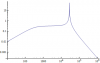
Plot the amplitude Ampl(w) and look at the plot.

Looking at the plot we see it is a low pass filter so we want to calculate G from Ampl(w) by setting w=0:
G=Ampl(0)=R3/(R1+R2+R3)

Now to find the -3db point we divide that by sqrt(2) and set it equal to the amplitude:
G/sqrt(2)=Ampl(w)

which is equal to:
(R3/(R1+R2+R3))/sqrt(2)=R3/sqrt((w*C1*R1*R3+w*C1*R1*R2)^2+(R3+R2+R1)^2)

Now at this point it is easier to insert the values for all the components, so we get:
1/(3*sqrt(2))=1000/sqrt(4.0*w^2+9000000)

and solving this for w we get:
w=-1500, and
w=1500

from which we reject the negative solution. So the -3db point frequency is:
fc=1500/(2*pi)

and this is approximately equal to 238.7 Hz.

Please note that when we are given the values for all of the components we can start with the transfer function using all the component values, so that immediately reduces all the algebra to that of using just complex numbers. For this example i waited more toward the end to insert the actual values because it is much cleaner to show the algebra than the numerical data. But when doing this calculations by hand it is almost always better to start with the numerical values in the transfer function right away because it reduces much quicker.
I leave this as an exercise for the reader here :)

Also note that when we used Ampl(0) above that is because we plotted the amplitude function and noted that it was a low pass filter. However, there may be times when the filter is not so well behaved so we may actually have to pick the value of w for this calculation using a little guesswork. This wont happen for most functions, but it is a possibility. Of course there is also the possibility that we are using this for a limited frequency range and then we might again have to pick this number by hand.
 

Attachments

  • CircuitRC-01.gif
    CircuitRC-01.gif
    4.2 KB · Views: 159
Last edited:
Also note that when we used Ampl(0) above that is because we plotted the amplitude function and noted that it was a low pass filter. However, there may be times when the filter is not so well behaved so we may actually have to pick the value of w for this calculation using a little guesswork. This wont happen for most functions, but it is a possibility. Of course there is also the possibility that we are using this for a limited frequency range and then we might again have to pick this number by hand.

A short comment regarding "guesswork":

Fortunately, such a "guesswork" is not necessary, if you write the transfer function in the so called "normal form".
That means: Divide the function T(s)=N(s)/D(s) by a suitable expression (In the above example: R3) with the aim to create a polynominal expression in the denominator D(s) that contains a constant "1".
That means, for a second order filter the transfer function has the form

T(s)=N(s)/D(s)=(ao+a1*s+a2*s^2)/(1+c*s+d*s^2)

In this case, you can derive an information on the filter type from the numerator N(s):

*low pass (n=1): a1=a2=b2=0
*low pass (n=2): a1=a2=0
*high pass (n=1): ao=a2=b2=0
*high pass (n=2): ao=a1=0
*band pass (n=2): ao=a2=0
*band stop (n=2): a1=0
*allpass (n=1): ao=1, a1=-b1, a2=b2=0
*allpass (n=2): ao01, 1=-b1, a2=b2
 
On the observation made about the -3dB point, I'd try and understand them now but looks esoteric for some part - that I admit is because I still have to learn my math properly! But thanks for bringing it out to give a holistic picture!

And I'd like to clarify: As long as the response in the circuit is the same flat response with the same roll off, with a gain of say 2, my corner frequency can be calculated by equating it to Vout/Vin = 2*0.707 = 1.414. In that case to find my cut off frequency I should look at the frequency that corresponds to the point 20 log (1.414) = + 3 db, instead of the usual -3db which is in case of the filter which has unity gain at the desired pass band frequency. Is this right?

Either way My cut off freq. is the point 3 db downward to whatever gain the high frequency pass band corresponds to, right? And since its 0 db for unity gain, we see -3 db. Also I noted Winterstone's post about the 'choice' of the 3 db point.
 
And I'd like to clarify: As long as the response in the circuit is the same flat response with the same roll off, with a gain of say 2, my corner frequency can be calculated by equating it to Vout/Vin = 2*0.707 = 1.414. In that case to find my cut off frequency I should look at the frequency that corresponds to the point 20 log (1.414) = + 3 db, instead of the usual -3db which is in case of the filter which has unity gain at the desired pass band frequency. Is this right?

Yes - that´s right because in your example the maximum gain is +6dB.
However, don`t forget you have to use the MAGNITUDE of the transfer function - that means: |Vout/Vin|=1.414 (for your example).
 
Also Wolfram Alpha is giving me Absoute values with 'i' in the solution. How can I get rid of this? Even If i evaluate the transfer function for the real part by prefixing Re|<insert transfer function>=0.707>| I still find the value having 'i' . I downloaded maxima, but I need more time to understand how that works. The electrician is able to get values without 'i' in mathematica though.
 
Hello again Winterstone and gauth,


Winterstone:
When i said guesswork, i meant guesswork. Simplifying down to a 2nd order filter we can eliminate the guesswork, but i dont know where you obtained the rule that we can only do 2nd order filters or less.

gauth:
If you do not have the correct Abs function in your software, you can always do this:
Ampl=sqrt(realpart^2+imagpart^2)

Remember that imagpart is the part that is multiplied by 'j', and you do not include the 'j' in this form. So for:
5+2j

the real part is 5 and the imag part is 2, not 2j.
 
When i said guesswork, i meant guesswork. Simplifying down to a 2nd order filter we can eliminate the guesswork, but i dont know where you obtained the rule that we can only do 2nd order filters or less.

Did you detect such a "rule" anywhere?
To the benefit of the questioner, I have tried to give some practical hint`s that have been proofed to be very useful for designing filters in practice. That`s all.
 
Hi gauthamtechie,

I don`t know how deep you intend to jump into the filter design, however, perhaps some additional explanations to the second order transfer function are helpful:

T(s)=N(s)/D(s)=(ao+a1*s+a2*s^2)/(1+c*s+d*s^2)

At first, this function plays a very specific role because one of the basic design procedures (cascade design) for higher order filters (n>2) is based on the series connection of separate sections of order n=2.

It is a very important property of the denominator function D(s) (for n=1 and n=2) - if written in "normal form" - that you can easily identify all the characteristic filter parameters:

1.) n=1

D(s)=(1+c*s)

c=1/pole frequency=1/wp=1/(2*Pi*fp) (wp identical to the 3-dB frequency wc)

2.) n=2

D(s)=(1+c*s+d*s^2)

d=(1/wp)^2
c=1/(wp*Qp)

wp=pole frequency (note that wp has a fixed relation to the 3-dB frequency, that depends on the selected filter approximation: Butterworth, Chebyshev,...); a corresponding scaling factor can be found in each filter book (tables with coefficients))
Qp=pole quality factor that determines the selected filter approximation: Butterworth, Chebyshev,...(Qp=0.707 for Butterworth response).
 
Thanks Winterstone, MrAl
I couldn't flog wolfram alpha enough to get me an answer without 'i' even if i specify Real part of the transfer function.

Anyway I will leave this and concentrate on designing it from scratch. I know I need a 3 pole high pass filter. I will choose a cut off frequency. Does anyone have an idea as to in which phase will Matlab be of use in the design process?
 
Did you detect such a "rule" anywhere?
To the benefit of the questioner, I have tried to give some practical hint`s that have been proofed to be very useful for designing filters in practice. That`s all.

Hello there Winterstone and gauth,

Well i was trying to be as general as possible. If you would like to do otherwise no problems here i guess, so from here it is your show :)

gauth:
It appears that Winterstone would like to help you here so rather than interfere with his fine teaching i'll step out for now. I'll check in at some point in the future to see how you are making out :)
 
Hi Electrician,

Regarding your matrix formation, I have one clarification. What if I had a voltage source Vnew in the Leg with the inductor as well? What will I equate this to - (Vx - V1)*(s C1) + Vx*(1/(s L1)) + (Vx - Va)*(s C2) = ??? Should I look into per unit values and stuff?

And this term: Vx*(1/(s L1)) will change to (Vx-Vnew)*(1/(s L1)) right ?
 
OMG after dealing with So many concatenation errors and all other "Try a shorter query Instead" and other issues in wolfram I finally got it!!!!!!!!!!!

this is where I got the Absolute value: https://www.wolframalpha.com/input/?i=[|%287.326*10^-14*s^3%29%2F%281%2B%287.326*10^-5*s%29%2B%283.2*10^-9*s^2%29%2B%287.326*10^-14*s^3%29%29|%3D%3D0.707]+for+s%3Df*6.28*i

Then I took the Mathematica plaintext input from Copy text option in this box where solution is provided assuming f is real:
fsns-png.74282


Then I input it in another wolfram page: https://www.wolframalpha.com/input/?i=ComplexExpand[1.814453511552*^-11+Abs[f^3%2F%281+%2B+%280.+%2B+0.000460073+I%29+f+-+%281.2620288*^-7+%2B+0.+I%29+f^2+-+%280.+%2B+1.814453511552*^-11+I%29+f^3%29]+%3D%3D+0.707]

And I finally got f=3333.83 !
 

Attachments

  • FSns.png
    FSns.png
    8 KB · Views: 261
Status
Not open for further replies.

Latest threads

Back
Top