Continue to Site

Welcome to our site!

Electro Tech is an online community (with over 170,000 members) who enjoy talking about and building electronic circuits, projects and gadgets. To participate you need to register. Registration is free. Click here to register now.

  • Welcome to our site! Electro Tech is an online community (with over 170,000 members) who enjoy talking about and building electronic circuits, projects and gadgets. To participate you need to register. Registration is free. Click here to register now.

What is the cut off frequency of this LC and RC combination?

Status
Not open for further replies.
What is the method to theoretically find the cut off frequency of this filter(image attached) which has an LC and also an R? How do I look at: As an LC followed by RC or T network followed by resistor?

Attached the screenshot of Filter: -3dB CutOFF.pngpoint is around 3.4 kHz in the AC sweep.
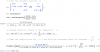
 
You can use a Laplace transform? C --> 1/sC; L --> sL; R --> R

Then use the voltage divider rule ([LATEX]{V_o^'}=\frac{{V_i^'} R_1}{R_1+R_2}[/LATEX]) to get [LATEX]\frac{V_o}{V_i} = \frac{\frac{1}{\frac{1}{sL}+\frac{1}{\frac{1}{sC_2}+R_1}}}{\frac{1}{sC_1}+\frac{1}{\frac{1}{sL}+\frac{1}{\frac{1}{sC_2}+R_1}}}\cdot \frac{R_1}{R_1+\frac{1}{sC_2}}[/LATEX]

You then solve for [LATEX]\omega[/LATEX] such that [LATEX]\left \| \frac{V_o}{V_i} \right \|=\frac{1}{\sqrt{2}}[/LATEX]

I just had a go and it turns into a right royal mess.
 
Last edited:
Dougy83, the result as given by you cannot be correct. Check - for example - the dimensions of the various expressions. They must be equal - but they are not.
More than that, by applying the voltage divider rule - which is possible, in principle - you should show the various expressions for X1, X2, X3 (use not ohmic symbols R1,2,3).
Such a circuit can quickly calculated using the "Substitution Theorem".
 
Dougy83, the result as given by you cannot be correct. Check - for example - the dimensions of the various expressions. They must be equal - but they are not.
Winterstone, you are correct re me being incorrect. I've updated the formula; it's worse than before.
Such a circuit can quickly calculated using the "Substitution Theorem".
Perhaps you could show how this is done.
 
Dougy83, the result as given by you cannot be correct. Check - for example - the dimensions of the various expressions. They must be equal - but they are not.
More than that, by applying the voltage divider rule - which is possible, in principle - you should show the various expressions for X1, X2, X3 (use not ohmic symbols R1,2,3).
Such a circuit can quickly calculated using the "Substitution Theorem".

I did not have time to check if the transfer function is entirely correct, but the units/dimensions look fine. Maybe I missed it, but where is the dimensional inconsistency?
 
Perhaps you could show how this is done.

You have applied it - perhaps without realizing.
At first, you have calculated the voltage across the inductance. Then you have replaced (substituted) this voltage with an ideal voltage source, which drives the last two parts R1 and C2..
This is allowed only because of the substitution theorem (To be found, for example, in "Desoer, Kuh: Basic Circuit Theory")
 
Hello there,


Electrician:
How did you known you could use sqrt(1/2) in your equation to solve for the cut off?
I ask because you did not show that.

All:
Matrix methods are good to know. This problem is simple though because for one thing all the component values are known.

To do the simplest analysis we only need to work in 2 dimensions throughout. That's because the complex impedance of any element is always of only two values:
(real,imag)
or stated as:
realpart+imagpart*j

and because we are given all the numerical values for every component, we can always reduce every step of the problem into just two dimensions. And because we want the output and the output is on the right side of the circuit, it would be convenient to work from left to right. We can do this using Norton and Thevenin theorems, working from left to right transforming the sources from one to the other and back again while keeping track of the complex impedances.

To start, we transform every C and L into it's complex impedance, we will call them then zC1, zC2, zL1. However it should be noted that these are simple NUMERICAL values once you use the values given. For example, zC1 is equal to -j/(w*C1) but because we already know the value of C1 it becomes simply:
-1e8*j/w
which has 0 real part and so we would write this as:
0-1e8*j/w.

That's the result of transforming C1 into it's complex impedance, and we note that this is just in 2 dimensions and that's how we can keep it throughout the remainder of the calculations.

So knowing this value and noting that V1 is in series with that, we can convert voltage source to a current source in parallel with C1. The current is V1/zC1 so we end up with:
I1=V1/(-1e8*j/w).

So we remove V1 and C1 and replace it with a parallel circuit with I1 and C1. That puts C1 directly in parallel with L1. Since we then have two impedances in parallel, we can compute their impedance Zp. We then have a current I1 in parallel with Zp, from which we can calculate V2 from V2=I1*Zp. We now have a circuit that has a single voltage source V2 in series with Zp, C2, and R1, so it is now reduced to a voltage divider. It is then simple to calculate the voltage across R1.

In the end we end up with a numerical transfer equation and we must PLOT this equation in order to determine what to do next because we do not yet know what kind of 'filter' it is such as:
1. Low pass
2. High pass
3. Band pass

We next determine the best equation to solve to determine the cut off.

I can show more detail if you would like. Basically what we do here is use Norton and Thevenin to reduce the circuit to a simple voltage divider, then calculate the voltage across R1, then determine what value to use in the equality equation to find the cut off. Then we actually find the cut off using the response. But the key idea is that we never have to calculate anything more than a single complex voltage or current and a single complex impedance to get the result, so it makes short work of these problems.
 
Hello there,


Electrician:
How did you known you could use sqrt(1/2) in your equation to solve for the cut off?
I ask because you did not show that.

I'll wager you that the OP knows. Let's ask him.

gauthamtechie, do you know why the sqrt(1/2) appears?
 
Hello again,


I had the feeling you did not want to answer that question. Dont be afraid. Go ahead, provide an answer, after all this is not a homework question is it?
<little chuckle>
Seriously though, i'd like to hear your take on this, and since you provided all the details i dont see why you would want to leave that one out.
 
Hi The Electrician.
Can you explain how did you get Y?
It was immediately? Simply took a look on circuit. Did you use regular kirchhoff’s laws or used a specific procedure?
Thank you.
MOR_AL
 
Hi,

Wasnt that simple nodal analysis?

Electrician:
If you dont want to answer my question i wont press you anymore. I just thought that eventually you might want to explain this to the OP. No problem if you dont care too, sorry if i sounded a bit 'demanding' there :)
 
MrAl
It is a High Pass frequency filter. The capacitors impedance at s --> ∞ is zero and the inductor impedance is ∞ at s --> ∞ (|va/vi| (at w --> ∞) = 0dB).
So the -3dB happens at |va/vi| = 0,707
 
Hi Electrician, I knew why you took 0.707 or rather SquareRoot(1/2).. And no it isn't a homework problem..

Vout/Vin is my transfer function. I need the cut off frequency. The cut off frequency is the -3 dB point; In terms of voltage that is the point where the output is 70.7% of the input which means Vout = 0.707 Vin ;And 0.707= Squareroot(1/2)
So I can equate the transfer function like this Vout/Vin = Squareroot(1/2)

Apparently The time difference is +10.5 hours between your place and mine; so i couldn't get back on your question in time!
 
Last edited:
The Electrician,

What tool did you use to compute this? Also I need to brush up my knowledge of Laplace Transforms since I am not able to yet get the Matrix you have in your answer..

And is there a way wherein Wolfram|Alpha can be used? What do I input though?
 
Last edited:
If the 3 nodes along the top of the circuit, left to right, are labeled V1, Vx, Va, you can write the 3 node equations with a TestCurrent of 1 amp applied to the input:

(V1-Vx)*(s C1) = TestCurrent

(Vx - V1)*(s C1) + Vx*(1/(s L1)) + (Vx - Va)*(s C2) = 0

(Va-Vx)*(s C2) + Va*(1/R1) = 0

Collect terms and you will have:

V1*(s C1) + Vx*(-s C1) + Va*(0) = 1 The 1 here is the test current.

V1*(-s C1) + Vx*(s(C1+C2)+1/(s L1)) + Va*(-s C2) = 0

V1*(0) + Vx*(-s C2) + Va*(s C2 + 1/R1) = 0

Solve these equations for V1, Vx and Va using whatever method you like. I inverted the matrix of coefficients and the voltages V1, Vx and Va are the first column of the inverse; columns 2 and 3 are not needed. Form the expression Va/V1. Substitute numerical values and the rest follows.
 
Hello again,


I had the feeling you did not want to answer that question. Dont be afraid. Go ahead, provide an answer, after all this is not a homework question is it?
<little chuckle>
Seriously though, i'd like to hear your take on this, and since you provided all the details i dont see why you would want to leave that one out.

I left it out because I judged that the OP knew already, and there was no need to waste his time and mine explaining something he already knew.
 
Thanks, I've learnt a lot of things.

Now I have to modify this filter to give me higher cut off frequency. Now, is it better I look at how to design this filter from scratch, which has a butterworth response?
 
Status
Not open for further replies.

Latest threads

New Articles From Microcontroller Tips

Back
Top