Electro Tech is an online community (with over 170,000 members) who enjoy talking about and building electronic circuits, projects and gadgets. To participate you need to register. Registration is free. Click here to register now.
Welcome to our site! Electro Tech is an online community (with over 170,000 members) who enjoy talking about and building electronic circuits, projects and gadgets. To participate you need to register. Registration is free. Click here to register now.
Because using a constant current source improves the regulation considerably, particularly if the input does vary, but just as importantly it allows the input voltage to be considerably closer to the output voltage than a simple resistor.
Thank you guys, and i want to know how to calculate the output current of this constant current source?
Please show me how to get onto the right path~!
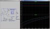
Here is a sim of what the current source puts out into a fixed load of 10V as a function of the input voltage varying from 20V to 60V and as the temperature varies from -25degC to 50degC. This is the way that it is used in the voltage regulator above...
Here is a sim when the input voltage is fixed at 50V showing the output current as a function of the output voltage and temperature. This normally the way a current source is characterized (to show the output impedance of the current source). In the voltage regulator, the output voltage is very close to 10V, so that is why I showed that case first.
Note that the current source works very well, but its current is a strong function of temperature...
Thank you very much for your simulation, Mike.
The result is intuitional, but I want something theoretic, such as formula or verbal description.
I know this whole circuit like a LDO, but I don't understand how this constant current source keep constant when input voltage has a wide range?
Here is a comparison of driving a 10V Zener using the current source vs just putting a resistor in series with it. Note that the current source improves the Zener's voltage regulation (slope of V(out1) is flatter than slope of V(out2), but temperature dependence is slightly better with only a resistor driving the Zener
If we want to get really carried away, we can use the shunt regulator as the reference for a constant current sink (Q3 and R2 in the attachment below) to replace the bias resistor in the original circuit.
This is a positive feedback circuit, and, as such, can power up in one of 2 stable states. The current source can either be off or on. We need to eliminate the off state.
I added another transistor and zener (Q4 and D2, and R3) for startup. Q4 cuts off as soon as it has done its job, and is effectively out of the circuit the rest of the time.
This is probably overkill for most applications, but it was a fun exercise. Note that the input voltage is swept from 12V to 50V.
It doesn't help temperature performance, of course.
This site uses cookies to help personalise content, tailor your experience and to keep you logged in if you register.
By continuing to use this site, you are consenting to our use of cookies.