Continue to Site

Welcome to our site!

Electro Tech is an online community (with over 170,000 members) who enjoy talking about and building electronic circuits, projects and gadgets. To participate you need to register. Registration is free. Click here to register now.

  • Welcome to our site! Electro Tech is an online community (with over 170,000 members) who enjoy talking about and building electronic circuits, projects and gadgets. To participate you need to register. Registration is free. Click here to register now.

Welder made with microwave oven transformer

Status
Not open for further replies.
Wouldn't like to guess how useful the technique is for a stick welder though. .

Actually you will find a lot of the higher end welder transformers are wound with flat, square, or rectangular windings instead of round windings.

Flattened winding gives the most surface area per cross sectional unit which helps with cooling. ;)
 
It should not lower the performances of the welder. For the capacitors, I am lost with the calculations needed. Something like a rule of thumb advice or just an approximate value would be more what I need as long as it is relatively sure that it will improve the welding.

The simplest method is to just use an amp meter and read your input amps at idle and keep adding capacitance until your amp reading reaches its lowest point. Too much capacitance after that will start moving the amps up again.


Also you want motor run capacitors not motor start capacitors. Motor start are short duty cycle high current devices that will burn up if used for more than a few seconds at a time out of a several minute duty cycle time.
 
Theres a term for flat windings, just cant remember it.
Not exactly easy for diy, but it does help heat dissipation.
 
Copper flashing is one of the most common types of flat copper sheet on roles.

These guys probably have what you are looking for.;)

**broken link removed**
 
Last edited:
Edgewise, thats what I was thinking of, see the pic below, its just a fancy name for bending the copper around the thinnest side to get the most on the winding.

Cool link TCM, theres nothing like that here in the UK.

edgewoundcoils.gif
 
Ooooohh, I'd love to have a go at making that!
 
The simplest method is to just use an amp meter and read your input amps at idle and keep adding capacitance until your amp reading reaches its lowest point. Too much capacitance after that will start moving the amps up again.


Also you want motor run capacitors not motor start capacitors. Motor start are short duty cycle high current devices that will burn up if used for more than a few seconds at a time out of a several minute duty cycle time.

Thanks!

To do that, I would need to have many run capacitors on hand. I don't have any.

I think that I will leave it as it is, I am happy with the performances anyway.
 
Last edited:
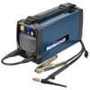
Last weekend I found a broken Tig/stick inverter welder at the flea market. Paid 30$. When I bought it, I was thinking that I could fix it and get a good machine for next to nothing. But I did not check it very much and when I arrived home I realized that it was Mastercraft welder, a brand from the Canadian Tire stores.

To make it short, I just despize this brand and I don't want any electric Mastercraft tool in my shop. This welder is a good example of wy I despize the brand. It is only 4 years old (the boards are dated Feb. 2008), the inside of it being immaculate making it very obvious that it has not worked a lot before dying. Do you think that the guy who bought it new had a good deal? Less than 4 years later, about only good for recycling! As I saw in the web It was selling for around 500$ at the store before being discontinued.

I decided not to try to fix it.

Here are the parts that I salvage from it (missing one board on the pictures).

**broken link removed**

**broken link removed**
 

Attachments

  • Tig1.png
    Tig1.png
    834.3 KB · Views: 320
  • Tig2.png
    Tig2.png
    919.4 KB · Views: 368
  • Tig4.jpg
    Tig4.jpg
    5.1 KB · Views: 299
Last edited:
I will use some of these parts for my MOT welder. With just the welding cables I am happy with this deal.

There is this part; is this what is called an inductor? Could it be used in my welder?
 

Attachments

  • Tig3.png
    Tig3.png
    998.8 KB · Views: 403
Last edited:
Hi,

That could be an inductor but might be a resistor, or an inductor designed with a specific resistance.
Do you have a schematic of what circuit it was used in?
 
No, I don't have a schematic. It would be dreaming to think that it is possible to get one.

This part seem to be just 23 turns of flat copper 1/4 inch by 1/16 with a big steel bolt in the middle. The bolt is isolated from the copper by a fiberglass tube and 2 rubber washers. No noticeable resistance seen on my multimeter.

One side of this part was directly connected to the positive plug of the welder, that is where you connect the exterior welding wire. The other side was connected to one of the 2 boards.
 
Last edited:
Its the reactance coil which is basically just a big lossy inductor hence its low tech design and yes you could use it in your welder.

I would be curious to see what influences it has on the weld puddling effects.
 
Last edited:
Inverter sets dont really 'need' and inductor to smooth the arc, that device is probably meant to prevent hf noise from getting onto the output leads.
I know its a killjoy thing to say however it probably isnt gonna be a high enough inductance to make much diffo in your circuit.
Chances are canadian tire didnt make that thing, stuff like that these days is usually rebranded from a chinese manufacturer.
I have a similar thing, I must have been fortunate as mine worked well, and has kept working well.
 
Since MOT saturate due to
1) insufficient iron in the core
2) insufficient inductance limiting primary current

(This is due to consumer economics as copper = $$$ and Silicon Iron = weight.)

We have a lot of heating going on under no load. (A secondary load decreases primary flux density)

One can either create an adjustable air gap by separating the E laminations from the I. and shimming the gap with an insulator. Easily done by filing off the weld with a dremel and shimming with hardboard etc. OR increase the Primary inductance by adding an inductor of some magnitude in series with the Primary. Often a second MOT is used for this.

Increasing the Turns/Volt in the Primary will be tough, I think they need to be doubled.

Then there is reducing the voltage at the secondary, variac anyone?

It has occurred to me to use regular steel sheet cut to strip, lacquered and stack as laminates to create a box around the MOT in an effort to increase the saturation limit of the iron core. But that requires some time I don't have right now.

here is some useful info.
**broken link removed**

EDIT one last interesting option is to place a triac in front of the transformer and chop the incoming sinewave, thus increasing the frequency of the supply. This has the effect of increasing the inductive impedance effect of the existing Primary and thus reducing the Turns/Volt requirement. Perhaps it might be better to rectify the supply and create a pulsed DC supply kinda like a switch mode PSU, with consequent efficiency gains. Depends on your app. Due to the iron laminations u can't bump the freq too high, eddy currents will kill efficiency. Just go high enough to eliminate the heating energy loss, prob 120Hz would be good.

https://www.electro-tech-online.com/threads/inductor-transformer-size-vs-frequency.111880/
 
Last edited:
Status
Not open for further replies.

Latest threads

New Articles From Microcontroller Tips

Back
Top