Continue to Site

Welcome to our site!

Electro Tech is an online community (with over 170,000 members) who enjoy talking about and building electronic circuits, projects and gadgets. To participate you need to register. Registration is free. Click here to register now.

  • Welcome to our site! Electro Tech is an online community (with over 170,000 members) who enjoy talking about and building electronic circuits, projects and gadgets. To participate you need to register. Registration is free. Click here to register now.

Weird 74LS90 counter problem

Status
Not open for further replies.

Torben

Well-Known Member
Hi all,

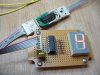
I'm having an interesting problem with the outputs of the 74LS90 chip. For quick background, I'm making a game scorer using 2 identical 74LS90/74LS47 circuits. Works great--except:

I have the main circuit on a central PCB, and want to mount the 7-seg displays remotely from the main board. I have 6-pin headers on the main board and 6-conductor ribbon cable running from there to the display board, where the 74LS74 decoder, current limit resistors, and 7seg display are.

Now this all works just dandy...*iff* my ribbon cable is less than about 60cm long. Any longer, and the 74LS90 starts counting funny...in fact, it will reliably jump straight from 3 to 12 (BCD, that is; when triggered while at 3, the outputs of the 74LS90 will go from HHLL to LLHH instead of going from HHLL to LLLH as it should).

Doesn't matter if there is anything on the far end of the ribbon cable, by the way. Just plugging a too-long ribbon cable into the header will cause the outputs of the 74LS90 to behave as described.

I have tried this with and without a 100nF cap on the power pins of the 74LS90 and nothing changed. However, I have a Mylar cap there now (I think--it's about 1cm x 1cm x ~0.3cm, and looks like a yellow core of
some kind inside a thin clear coating). I'm going to try different kinds
(i.e. ceramic, electrolytic) to see if that helps.

So finally my questions:

1) Does anybody have any links to information on how long a line you
can drive from the outputs of a 74LS90?

2) Would you typically want to drive the longer lines using transistor buffers or something (I gather there are IC buffers with several built in)?

3) Any other hints/links to good reading? I've googled the heck out of this one. :)


Thanks all who read this!

Torben
 
Quick check - can you try using the long cable, but connect the power and grounds together with a short clip leads?

How big are these displays and how much current are you driving into them?
Ribbon cable is 28 gauge and ends up being ~.25Ohm/meter, which combined with the low thresholds of LS chips means bad things could happen on the clock edges.
 
Thanks for the reply!

hjames said:
Quick check - can you try using the long cable, but connect the power and grounds together with a short clip leads?

Just short Vcc to ground? At the far (display) end of the cable? Not
sure where you mean here. Or does it even matter?

How big are these displays and how much current are you driving into them?
Ribbon cable is 28 gauge and ends up being ~.25Ohm/meter, which combined with the low thresholds of LS chips means bad things could happen on the clock edges.

They're 1.9cm x 2.7cm (housing). Model # is KLD-3401AR. They work just great when the ribbon cable is <= ~60cm. And the problem appears to be independent of the display board; I can produce the problem by simply hanging a too-long cable off the main board header, with nothing attached.

It's like the cable is acting like an antenna or capacitor or something, and affecting the counting behaviour of the 7490. The 74LS90 shouldn't even count to 12 BCD (or at least that truth value never shows up in the data sheets I have checked: Motorola and Fairchild).

I'm going to see whether a hex non-inverting buffer on the ribbon cable helps. Otherwise, I plan to just alter the build plans to take the cable length limit into account. :) Wish I knew what the problem was, though...and the fact that around 10cm of ribbon cable makes a difference is a little nerve-wracking,


Anybody recognize anything like this?


Torben
 
Torben said:
I'm going to see whether a hex non-inverting buffer on the ribbon cable helps.

The long cable had added large capacitance to the Q outputs of 74LS90. The internal logic of 74LS90 requires these Q outputs to change states quickly in order for the decoder inside to obtain divide by 2 and divide by 5 as it is basically a 4-bit counter with logic gating to make a decade counter.

The idea of using hex non-inverting buffer between these Q outputs and ribbon cable will definitely helps to isolate the current problem.

Added later: You'll need two hex buffer ICs, you may consider 74LS244 which has eight buffers per IC so you only need one. Or you might be able to "get away" using 100 ohm resistors in series with the connections at these Q outputs but I would not recommend it for serious application.
 
Last edited:
7490

The TTL 7490 are very fast switching IC's and just time lag and capacitance will cause erratic counting with long wires between the 7490 and 7447's.

Check you 5 volts voltage.
The loading of the 7447's and LED display may be too high for the ribbon cable and cause too much volts drop for the 7447's to decode properly.
 
OK, the hex buffer did it! I don't know whether I did this right, but it works: I can now drive my long cable off the end of the shorter (60cm) one I was using before. That's more than I was hoping for in a first test.

I used a 4010 non-inverting hex buffer, 'cause that's what I had around.

I hooked up Vcc from the main board to Vcc and Vdd on the 4010 hex buffer, put GND from the main board to Vss on the 4010, and put the signal lines through 4 of the buffers. Tossed on a couple of headers and I've got a display cable booster.

Anyway, I've attached a shot of the prototype display board displaying a "4" over more than a meter of ribbon cable, which qualifies as a success to me. (Of course you can't see all the cable but I'm really happy about this so trust me--it's there). For the record, before the buffer it would have displayed a "4" with no leg--a BCD 12, which the 74LS90 shouldn't produce at all when wired for BCD counting.

Thanks for the help and for the backup on the ribbon cable capacitance hypothesis. I don't have the gear to test capacitance to that kind of tolerance so it's all down to knowing the rules, at that level.

n.b. I know I'm using brutal techniques and ancient tech but I'm trying to learn and I had 70LS90s and 74LS47s around so that's what I based the design on. I do have an ARM SBC I could use (and I know that stuff way better) but this is more fun right now.

Hm. Anybody think I could use a cap on the 4010? Appears to work without it, but things have a funny way of working slightly differently once they've escaped my bench.


Thanks for the help!

Torben
 

Attachments

  • 4010_7seg_small.jpg
    4010_7seg_small.jpg
    53.3 KB · Views: 290
Last edited:
Torben said:
OK, the hex buffer did it! I don't know whether I did this right, but it works: I can now drive my long cable off the end of the shorter (60cm) one I was using before. That's more than I was hoping for in a first test.

Good news.

You would need to place the buffer close to the outputs of 74LS90 in your final design, not at the end of a 60cm cable.

Remember to also tie the inputs of the remaining two unused buffers on the 4010 to either ground or +V. Their outputs can be left unconnected.

A capacitor on the buffer would not make a noticeable difference as the logic levels are stable and no clocking is involved. The 74LS47 will never display a wrong result in this case.
 
eblc1388 said:
Good news.

You would need to place the buffer close to the outputs of 74LS90 in your final design, not at the end of a 60cm cable.

OK, cool. I suspected something like that--I was figuring I was pretty close to the end of the tolerance range when testing that way, which is why I was surprised to see the test work. I'll definitely put as little distance as I can between the buffer and the main board. The main board is finished though, so the best I can do is 3-5cm. But if it appears to work fine at 60cm then anything <= ~10cm should be OK for my purposes. (I don't intend to try to sell this thing, just learn from it.)

Remember to also tie the inputs of the remaining two unused buffers on the 4010 to either ground or +V. Their outputs can be left unconnected.

Now that you've told me to do that, I'll remember.

I hope.

(um....why?)

A capacitor on the buffer would not make a noticeable difference as the logic levels are stable and no clocking is involved. The 74LS47 will never display a wrong result in this case.

Ok, cool. Good to know (hell, at my point, *anything* is good to know).


Thanks!

Torben
 
CMOS gates input are of very high impedance.

If it is not tie to a fixed voltage, then electric field, circuit board leakage etc... all contribute to change the pin voltage randomly. In case of clocking circuits, random clocks signals will be generated.

In your case, the CMOS gate output would switch randomly, and cause a lot of current to flow if the input pin is at or near about 50% of the total supply voltage for a long time.
 
eblc1388 said:
CMOS gates input are of very high impedance.

If it is not tie to a fixed voltage, then electric field, circuit board leakage etc... all contribute to change the pin voltage randomly. In case of clocking circuits, random clocks signals will be generated.

In your case, the CMOS gate output would switch randomly, and cause a lot of current to flow if the input pin is at or near about 50% of the total supply voltage for a long time.

Hoofta. That's good to know. Thanks for taking the time to explain!

One more question: this phantom gate switching would happen on the gates I'm using, if the gates I'm not are not tied to Vcc or gnd? That's what I think you said, anyway.


Torben
 
The random switching occurs only on gates which do not have a well defined voltage on their inputs.

Any gates that are in use will have well defined voltages on their inputs so will not be affected. However, random switching of other gates would causes noise and affect performance of these in use gates.

That said, un-used gates with floating inputs could stay in the switching threshold mode and cause a very large current drain to the IC. This is enough to heat it up and destroy it eventually.
 
eblc1388 said:
The random switching occurs only on gates which do not have a well defined voltage on their inputs.

Any gates that are in use will have well defined voltages on their inputs so will not be affected. However, random switching of other gates would causes noise and affect performance of these in use gates.

That said, un-used gates with floating inputs could stay in the switching threshold mode and cause a very large current drain to the IC. This is enough to heat it up and destroy it eventually.

Ah. Yes, that would be bad. I'll make sure to keep an eye out for that sort of thing with other stuff I run into as well.


Thanks again!

Torben
 
Status
Not open for further replies.

Latest threads

New Articles From Microcontroller Tips

Back
Top