Continue to Site

Welcome to our site!

Electro Tech is an online community (with over 170,000 members) who enjoy talking about and building electronic circuits, projects and gadgets. To participate you need to register. Registration is free. Click here to register now.

  • Welcome to our site! Electro Tech is an online community (with over 170,000 members) who enjoy talking about and building electronic circuits, projects and gadgets. To participate you need to register. Registration is free. Click here to register now.

Wadley Loop Design

Status
Not open for further replies.

pulzar

New Member
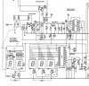
I'm a newbie to this forum trying to get some expertise on a problem I have repairing a Realistic DX-302 short wave radio. This radio was (still is) a nightmare. Some of the parts were replaced with non-replacement parts and some "new" parts were added which are not part of the schematic. Anyway most of the radio is now working except that the MHz tuning is not tracking properly. The service manual says that the MHz oscillator should be 55.5 MHz when the dial says "0", 56.5 for "1", 57.5 for "2" ... 83.5 MHz for "28" and 84.5 for "29". So this gives a total of 30 freqs for 30 numbers; so far so good. On this radio the "0" indicator (for 0 to 999 Khz) tunes perfectly at 53.5. I cannot get it to tune or track per the service manual. I can tune the oscillator for the correct frequency but then it doesn't receive any stations. If I tune for a station then it's good for only that MHz and doesn't track so WWV will be on 7.000 Mhz instead of 5.000 Mhz and some of the bands are dead because the mute cutes in between bands where the signal should be. It's a complicated problem because the MHz readout is actually a digital switch controlled by the MHz variable capacitor. My question is could someone take a look at the schematic and see what components are critical with the oscillator circuit that might make it tune off the desired freqs? Q401 is the 1st oscillator on the schematic. Thanks in advance! :(
 

Attachments

  • Wadley_1st-oscillator.jpg
    Wadley_1st-oscillator.jpg
    189.6 KB · Views: 899
The service manual says that the MHz oscillator should be 55.5 MHz when the dial says "0", 56.5 for "1", 57.5 for "2" ... 83.5 MHz for "28" and 84.5 for "29". So this gives a total of 30 freqs for 30 numbers; so far so good. On this radio the "0" indicator (for 0 to 999 Khz) tunes perfectly at 53.5. I cannot get it to tune or track per the service manual.
Do you have a suitable frequency counter to measure the oscillator frequency?, otherwise getting the tracking right will be a hard job.

I can tune the oscillator for the correct frequency but then it doesn't receive any stations. If I tune for a station then it's good for only that MHz and doesn't track so WWV will be on 7.000 Mhz instead of 5.000 Mhz and some of the bands are dead because the mute cutes in between bands where the signal should be.
While doing a quick internet search for a picture of a DX302, I came across this:

One of the hints suggests removing R227 which will stop the mute from operating between Mhz steps, thus helping in situations like yours where the tracking is all over the place.

My question is could someone take a look at the schematic and see what components are critical with the oscillator circuit that might make it tune off the desired freqs?
C403, C404 and T401 are the basic frequency determining components of the Mhz oscillator. T401 should be adjusted at the low frequency end of the tuning range (55.5Mhz)
VC5 is the Mhz tune capacitor (obviously).
TC402 is the trimmer capacitor which should be adjusted at the high frequency end of the tuning range (84.5Mhz).
C401 and TC402 are the padder capacitors, these set the range of the tuning capacitor, and should be adjusted so that rotating the tuning capacitor from 0 to 29.5 on the frequency display gives a change of 29.5 Mhz in the oscillator frequency.

I think that is all that I can tell you for now, good luck in getting is set up correctly.

JimB
 
More progress on the Wadley loop.

I've got the 1st oscillator operating according to the manual (55.5 for 0 and 84.5 for 29 indicated); there is a slight mistracking but it's not too bad. Now back to what seems to be the main problem: everything is shifted up 3 Mhz. When I tune to 2.000 MHz on the radio I'm picking up WWV @ 5.000 MHz. When I tune to 7.000 MHz I pick up WWV @ 10.000 and when I tune to 12.000 MHz I pick up WWV @ 15.000 MHz. The preselector is correct for the WWV freqs; that is if the radio is tuned to 7.000, I must tune the preselector to 10.000 to pick up WWV. If I tune the preselector to match the indicated freq then I pick up nothing anywhere. I've scoped the oscillator and it's amplitude is ~33mV @ 55.5 MHz but goes down to ~12 mV @ 84.5 MHz. I'm not sure if that can be leveled out or if it even matters.

Any help would be appreciated.
 
Making some progress

I did a lot of checking of the MHz oscillator and noticed that I could never reach 84.5 MHz (29 MHz on the readout) and then I noticed that TC401 was totally open so I need a little less capacitance. C401 is in parallel with TC401 and checking C401 I notced that it was actually 2 caps in parallel - a 150 pF + 30 pF which would of course give 180 pF but since I needed less capacitance I removed the 30 pF and now I can get to 84.5 and tracking is fairly good with the IF's peaking fairly close to each MHz readout.

Now the really big problem :eek: - With the MHz up to specs with the service manual it will not pick up as indicated. The indicated MHz reading is shifted up by 3 MHz. So if I want to pick up WWV on 5 MHz I have to tune to 7 MHz and so on and so fourth which means I cannot receive anything below 3 MHz (0.000 MHz indicated). This is really wierd and I really don't have a clue how this is happening.

Any help from the wizard would be kindly appreciated.

Thanks,
 
Stitching your two posts together into one reply as coherently as I can!
For some reason I seemed to miss your post on 2nd Oct?

I've got the 1st oscillator operating according to the manual (55.5 for 0 and 84.5 for 29 indicated); there is a slight mistracking but it's not too bad.
I assume that this is measured with a frequency counter at TP401?
In the manual which I managed to find on the net, it mentions to use a buffer amplifier between the counter and TP401, are you using a buffer?
If not, the lead from the counter could be loading the oscillator. So when you adjust the oscillator and then disconnect the counter, the oscillator runs at a higher frequency than you expect. Which ties in with your next statement:
Now back to what seems to be the main problem: everything is shifted up 3 Mhz. When I tune to 2.000 MHz on the radio I'm picking up WWV @ 5.000 MHz. When I tune to 7.000 MHz I pick up WWV @ 10.000 and when I tune to 12.000 MHz I pick up WWV @ 15.000 MHz.

The preselector is correct for the WWV freqs; that is if the radio is tuned to 7.000, I must tune the preselector to 10.000 to pick up WWV. If I tune the preselector to match the indicated freq then I pick up nothing anywhere.
Which appears to confirm that the Mhz oscillator is running high in frequency.
I've scoped the oscillator and it's amplitude is ~33mV @ 55.5 MHz but goes down to ~12 mV @ 84.5 MHz. I'm not sure if that can be leveled out or if it even matters.
Dont worry about it. Also, what is the bandwidth of the scope? If it is less than 100Mhz, the diplayed amplitude will be lower.


I did a lot of checking of the MHz oscillator and noticed that I could never reach 84.5 MHz (29 MHz on the readout) and then I noticed that TC401 was totally open so I need a little less capacitance. C401 is in parallel with TC401 and checking C401 I notced that it was actually 2 caps in parallel - a 150 pF + 30 pF which would of course give 180 pF but since I needed less capacitance I removed the 30 pF and now I can get to 84.5 and tracking is fairly good with the IF's peaking fairly close to each MHz readout.
Hmm, a major assault on the oscillator!
I cant help but think that you are loading the oscillator with the counter so that it is running at a lower frequency, as I said above.

For a test, see if you can hear WWV or anything else for that matter on the correct 1 Mhz segment by leaving the counter connected to the oscillator.
If you do, I suggest that you restore the oscillator circuit, build the buffer amplifier and try again.

JimB
 
Last edited:
One of my posts got lost (I thought forever) in the server debacle and there is some duplication; sorry about that!

I guess I failed to mention that I am using the 2SK19 FET buffer to measure the freq (with a 2.7 GHz freq counter). My scope is only 35MHz but the values I measured are fixed and relative to a constant voltage scale. I've checked the oscillator with and without the probe connected to the buffer and there is no effect at all on the freq so the buffer is doing its job very well. So, with my modified oscillator circuit everything seems to be in order except for the 3MHz shift. I mistyped a number so to make it clear here are the pre-selector, indicated and actual freqs:

pre-sel Indicated Actual
3 MHz 0.000 MHz 3 MHz
5 MHz 2.000 MHz 5 MHz (WWV @ 5 MHz)
10 MHz 7.000 MHz 10 MHz (WWV @ 10 MHz)
( et al. down the line )

If I change the pre-selector off freq then the freq disappears so I feel confident that the correct freq is what the pre-selector is indicating. The fact that the actual MHz display is off by 3 MHz is really baffling.

With all the problems with this receiver and the obvious tinkering (slaughter) by the previous owner I'm wondering if the oscillator transformer T401 has been changed. Would that cause a shift?

Also one of my biggest problems at the start of the calibration was the horror of finding that the IC201 has been replaced by one MPF-102 FET. That IC (SN76514N) is no longer available but I fabricated a substitute using an IC (LM1496) and external resistors that seems to work very well. With the FET in place I could not get any waveform from the 52.5 IF; now with my modified LM1496 in place I get a good 52.5 waveform off each IF transformer (peaked for 52.5) and into the 2nd mixer. I hope that's not causing any problem.

BTW the KHz oscillator is bang on although there is some backlash with the dial so that may be a mechanical problem.
 
One of my posts got lost (I thought forever) in the server debacle and there is some duplication; sorry about that!

I guess I failed to mention that I am using the 2SK19 FET buffer to measure the freq (with a 2.7 GHz freq counter). My scope is only 35MHz but the values I measured are fixed and relative to a constant voltage scale. I've checked the oscillator with and without the probe connected to the buffer and there is no effect at all on the freq so the buffer is doing its job very well. So, with my modified oscillator circuit everything seems to be in order except for the 3MHz shift. I mistyped a number so to make it clear here are the pre-selector, indicated and actual freqs:

pre-sel Indicated Actual
3 MHz 0.000 MHz 3 MHz
5 MHz 2.000 MHz 5 MHz (WWV @ 5 MHz)
10 MHz 7.000 MHz 10 MHz (WWV @ 10 MHz)
( et al. down the line )

If I change the pre-selector off freq then the freq disappears so I feel confident that the correct freq is what the pre-selector is indicating. The fact that the actual MHz display is off by 3 MHz is really baffling.
OK I think I understand that.

With all the problems with this receiver and the obvious tinkering (slaughter) by the previous owner I'm wondering if the oscillator transformer T401 has been changed. Would that cause a shift?
Changing T401 or adjusting its core will certainly affect the Mhz oscillator, but you seem to have that tamed now, dont worry about it for now.

Also one of my biggest problems at the start of the calibration was the horror of finding that the IC201 has been replaced by one MPF-102 FET. That IC (SN76514N) is no longer available but I fabricated a substitute using an IC (LM1496) and external resistors that seems to work very well. With the FET in place I could not get any waveform from the 52.5 IF; now with my modified LM1496 in place I get a good 52.5 waveform off each IF transformer (peaked for 52.5) and into the 2nd mixer. I hope that's not causing any problem.
Having given this some thought, are you sure that you are getting 52.5Mhz?
The inputs to IC201 are the Mhz oscillator and a "comb" of 1Mhz signals, L212 to L219 must be tuned so that only the 52.5 Mhz output of the IC201 mixer is amplified, I suspect that there is a significant 55.5Mhz content, giving the 3 Mhz shift in the tuning.

JimB
 
You might be on to something there. I tried to measure the waveform at the end of the 52.5 IF (L219) and it's low enough in amplitude that my bench counter oscillates around 50 to 52 but my handheld shows a pretty consistent 49.5 MHz which might explain the problem as you suspected. However, all the coils have a nice peak on the scope so I find it hard to believe that a coil designed for 52.5 will peak on a freq of 49.5. Does that mean my IC201 substitute is the culprit?
 
You might be on to something there. I tried to measure the waveform at the end of the 52.5 IF (L219) and it's low enough in amplitude that my bench counter oscillates around 50 to 52 but my handheld shows a pretty consistent 49.5 MHz which might explain the problem as you suspected.
OK

However, all the coils have a nice peak on the scope so I find it hard to believe that a coil designed for 52.5 will peak on a freq of 49.5. Does that mean my IC201 substitute is the culprit?
I think that IC201 is fine.
It is not so much that the coil is designed for 52.5 Mhz, it is just that it has an adjustable core and its inductance can be varied over quite a large range, maybe a ratio of 1.5:1 or more. So, adusting from 52.5 to 49.5 Mhz would be no problem.

To adjust the 2nd local oscillator amplifier, the handbook suggests using a sweep generator which I assume you do not have.
The tuning of this amplifier is critical to the correct operation of the Wadley Loop.

My best suggestion is that you obtain a signal source which can be set to 52.5 Mhz and injected into the amplifier as a test signal while you tune the inductors.
This signal source could be a simple home made oscillator.

JimB
 
Well I think that's really the problem; now fixing it!! I have 2 sig gens; one is an old Heathkit with feeble output above 40 MHz. The other is a robust military URM-25D which just bearly makes it to 51 MHz. I've been wanting a sweep generator so I think I will check out EBay for some good bargains. I really need something that gets in the UHF spectrum so I can tweak my scanners which go above 1 GHz. Wavetek seems to have the market share and they look like they are built like tanks. If you have any experience with sweep gens, do they also function as a dedicated signal generator (without the sweep)? The ones I've seen have a very limited scale but I do have a very accurate freq counter as long as the signal isn't too weak so I could tweak it using the counter but how stable it would be is another matter. If not then I guess I need to get both a sig gen as well as a sweep gen. I would probably need both anyway to inject a marker for the sweep.

Any comments?
 
While the handbook suggests a sweep generator, I would be quite happy just using a decent signal generator.
Note that I said signal generator not oscillator.
Signal Generator infers a piece of equipment which is intended for serious RF work. I will have a stable frequency, the output level will be calibrated and there will be an accurate attenuator to reduce the output to very low levels for receiver testing, and it will have modulation, usually both AM and FM.

I have an HP8640B which was give to me some years ago, (I thought that all my birthdays had come at once!).
These can be had quite cheaply and their performance is very good.
But beware, there are some fragile plastic parts inside, including some bevel gears, these have a habit of crecking and breaking over time, also some of the electronic components in there are now pure unobtainium, these things were designed in the mid 1970s but were the Rolls Royce of signal generators in their day.

I have no recomendations to make on sweep generators.
I have an old HP spectrum analyser and I managed to get a matching tracking generator for it last year. Very useful for sorting out filters etc, could sort out your problem in no time!

JimB
 
I really appreciate your help. I will have to wait a bit for some better test equipment to really get this radio running again and it's probably costing way more than it's worth but I've found that "the more I tinker, the more I learn" so I'm chalking it up to a nice training experience. I really want a Wadley circuit in my radio collection so I hope some day to have it displayed. The DX302 is really terrible for casual listening because you need three hands to cruise the dials but I think it really looks nice anyway.

Gary
 
Status
Not open for further replies.

Latest threads

New Articles From Microcontroller Tips

Back
Top