Continue to Site

Welcome to our site!

Electro Tech is an online community (with over 170,000 members) who enjoy talking about and building electronic circuits, projects and gadgets. To participate you need to register. Registration is free. Click here to register now.

  • Welcome to our site! Electro Tech is an online community (with over 170,000 members) who enjoy talking about and building electronic circuits, projects and gadgets. To participate you need to register. Registration is free. Click here to register now.

VU meter not working. Dynacord Echocord Super 76

Status
Not open for further replies.

Rorut

Member
I bought myself an old Echo. The VU meter does not work. Measuring voltage over it in DC mode gives 9mv. Measuring Ohm over it turned off the needle goes up all the way smooth and back smooth (nothing happens in mega or kiloohm). Seems to be a circuit problem. Anyone worked with these machines before? Is the circuit inside located in a problematic position?
Everything else seems to work fine.
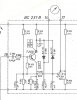
Schematic attached.
 

Attachments

  • dynacord_echocord_super_76_schematic_1972.pdf
    1,001.1 KB · Views: 107
  • 3B601FA2-E911-4754-933F-FA9ECF5276E1.jpeg
    3B601FA2-E911-4754-933F-FA9ECF5276E1.jpeg
    402.7 KB · Views: 93
Is the circuit inside located in a problematic position?
A strange expression in English.

Everything else seems to work fine
If the equipment is otherwise working normally, then the fault is almost certainly in the fragment of the circuit around transistor T200.

JimB
 
English is not my native language. What I tried to say was is if the pcb where the logic related to the VU meter is located in a place that is difficult to reach whithout taking everything apart. Please tell me how to adjust my expression. Thank you
 
What are the voltages at the collector and emitter of T200?
 
English is not my native language.
Yes I realise that, and I did understand what you were trying to say.
A better way to say it may be " Could the problem be in this part of the circuit?"

JimB
 
The first thing I would do is replace the 5 electros. 1u 1u 1u 10u 100u This will cost you $1.00 The VU meter will now work.
 
Opened it up. A lots of cables attached everywhere. Blue circle measured between 13 and ground gives 33v DC. Green circle is from VU meter. Any ideas where the transistor is? Guess I need everything connected for making measurments and to reach the other side of that board I probably need to desolder a lot of connections.

If it is not possible to make any measurments from this side as it is maybe one solution can be to desolder all cables, take the card out and replace all ellyt capacitors and/or any other components that may be old and then connect it all back and hope for the best? Dont know but that solution feels a bit difficult
 

Attachments

  • 74670DC6-AEAC-4A32-AF10-5995D528252C.jpeg
    74670DC6-AEAC-4A32-AF10-5995D528252C.jpeg
    765.1 KB · Views: 98
  • 8B4C0D5F-C2F0-4A2C-AB01-344D4ED46DBD.jpeg
    8B4C0D5F-C2F0-4A2C-AB01-344D4ED46DBD.jpeg
    1.9 MB · Views: 90
  • A1319E7D-C595-42FC-8798-DF0127234721.jpeg
    A1319E7D-C595-42FC-8798-DF0127234721.jpeg
    1.2 MB · Views: 88
  • FC48FA01-90A1-4A21-8A86-CA25206469D1.jpeg
    FC48FA01-90A1-4A21-8A86-CA25206469D1.jpeg
    564.6 KB · Views: 95
Last edited:
Blue circle measured between 13 and ground gives 33v DC.
That looks OK.

Any ideas where the transistor is?
Unfortunately no.

Guess I need everything connected for making measurments
Yes.

to resch (reach) the other side of that board I probably need to desolder a lot of connections.
Try it first without disconnecting.
It may be possible to move the board sufficiently to see the component side of the board.

That unit is a fine example of something which was built with no thought given to faultfinding and maintenance.

JimB
 
This sucks. Thinking is there any good 2 to 4 female/male connections I can buy and add to all places where a lot of cables go? Would make it easier to disconnect for future service aswell.
 
Looks like 4 screws holding the board in place. If you remove them and the cable ties you might be lucky and have enough cable slack to turn the board enough to get access to the underside.
 
Looks like 4 screws holding the board in place. If you remove them and the cable ties you might be lucky and have enough cable slack to turn the board enough to get access to the underside.
Checked again. That will not work. Some cables are to short. Measured nr 19 and that gave me 0v in both DC and AC if that could point me in any direction...
Dc started at 4-5v and kept going down until 0.02v.

Maybe I found where the transistor is. Not 100% sure but in the red circle I get measurements from top DC 0v middle 2.3v and bottom 14.9v. Also I get a resistance connected to the bottom 2.7K.
Probably need to get it apart to be sure :(
 
Last edited:
Ok now I have found the transistor and made some measurements.
Used a 1khz test tone and som music.
Look at the image for results and measurments.
transistor.jpg
 
Last edited:
Looks like T200 isn't conducting. C should be about 15V and E should be about 1.8V (I think. Difficult to read the schematic).
Some possibilities:
1) T200 is dead,
2) R201 or R203 has gone high resistance or open circuit,
3) bad solder joint at either end of those resistors,
4) R202 or C201 or C205 is short circuit.
 
I agree with alec_t.

Just to confirm, measure the voltage between emitter and base, it should be about 0.6V.
My guess is that you will see about 3v, in which case T200 is dead.

JimB
 
It is time to replace T200 then.

JimB
 
Could I place it from the bottom side insted of taking everything apart. That would make it alot more easy. The old one must be desoldered first?
 
Status
Not open for further replies.

Latest threads

New Articles From Microcontroller Tips

Back
Top