Continue to Site

Welcome to our site!

Electro Tech is an online community (with over 170,000 members) who enjoy talking about and building electronic circuits, projects and gadgets. To participate you need to register. Registration is free. Click here to register now.

  • Welcome to our site! Electro Tech is an online community (with over 170,000 members) who enjoy talking about and building electronic circuits, projects and gadgets. To participate you need to register. Registration is free. Click here to register now.

volume attenuator LDR

arivel

Member
HI .
I thought I'd ask for an opinion on something.
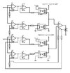
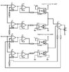
it is a volume attenuator that uses 2 pairs of LDRs as you can see in the photo.
the two opamp chains for each LDR pair are used to ensure that as the input signal varies, when the value of a photoresistor increases, the other connected one decreases in synchrony. same thing for the other branch being 2 channels.
the curves of the LDRs are not equal therefore the task of U7 is to vary the output voltage of the opamp chain of the group below to vary the voltage that controls the led of the photocouplers and obtain the same attenuation value of the 2 channels.
it is true that the u7 opamp inputs are on the audio path but having very high input impedance it is irrelevant.
it is a draft that I tried in the simulator but if I don't connect the U7 output to create the feedback of the other opamps it works but not anymore if I connect .
of course everything that comes before is missing but it is not necessary to know it.
what do you think about it ? Can it work if done right?
 

Attachments

  • ldr+fda.jpg
    ldr+fda.jpg
    75.4 KB · Views: 199
I'd have the opto LED driver opamps in current feedback, rather than "open ended" as you have them.

eg. Connect the opamp output to LED anode and put the load resistor from the cathode to 0V, with the cathode-resistor junction connecting to the inverting input. The non-inverting input voltage will then directly control LED current.

It should give a rather more linear response, as the LED voltage drop is not involved (as long as the supply is adequate and you select the load resistor appropriately.

Use one input opamp to feed the upper driver, then the other as a unity gain inverter with an appropriate bias on the noninverting input, to feed the lower driver.

I do not see how the "matching" feedback can work, unless you add a DC bias at the audio inputs to provide it with voltages to compare, and a lot! of low pass filtering on the comparison amp circuit, so it does not respond at all to anything within the audio range.
 
It's not entirely clear to me what you wrote. Unfortunately I don't master the English language well.
Maybe I'd better clarify one thing.
u1-u5-u8-u9 are commanded by a logarithmic scale . I don't know if this is what you need to know
 
I'd have the opto LED driver opamps in current feedback, rather than "open ended" as you have them.

eg. Connect the opamp output to LED anode and put the load resistor from the cathode to 0V, with the cathode-resistor junction connecting to the inverting input. The non-inverting input voltage will then directly control LED current.

It should give a rather more linear response, as the LED voltage drop is not involved (as long as the supply is adequate and you select the load resistor appropriately.

Use one input opamp to feed the upper driver, then the other as a unity gain inverter with an appropriate bias on the noninverting input, to feed the lower driver.

I do not see how the "matching" feedback can work, unless you add a DC bias at the audio inputs to provide it with voltages to compare, and a lot! of low pass filtering on the comparison amp circuit, so it does not respond at all to anything within the audio range.
would you be so kind as to use different words to explain again what you wrote?
 
This is what is being described. See if you can match the description to the drawing. Note in particular that voltage
V(i) = V(fb) as voltage source V1 is being swept over the range 0 to 6 VDC

1679598515521.png
 
It seems you want to make an optical-isolated stereo attenuator that has only a 20 dB control range in resistance at 5mA used as a differential pair to get 40 dB range. (slightly more with high current.)

There are no specs for matching components or the resistance error at some fixed nominal current.

1679612607391.png


Is that enough range ?
Is there a reason you need optical isolation perhaps due to common-mode (CM) interference?
There are many ways to control stereo attenuation but it depends on all your expectations.

such as noise levels , distortion, and linear or log control of audio which has a wide log range.
 
Last edited:
It seems you want to make an optical-isolated stereo attenuator that has only a 20 dB control range in resistance at 5mA used as a differential pair to get 40 dB range. (slightly more with high current.)

There are no specs for matching components or the resistance error at some fixed nominal current.

View attachment 140930

Is that enough range ?
Is there a reason you need optical isolation perhaps due to common-mode (CM) interference?
There are many ways to control stereo attenuation but it depends on all your expectations.

such as noise levels , distortion, and linear or log control of audio which has a wide log range.
it's the only way i know to separate the audio path from the control signal making use of photoresistors . what other ways do you know ?. maybe making use of magnetic resistors?.
yes, in fact there is another problem. if the power supply of the led diode contains some ripple, this is transferred to the photoresistors. if you know a trick to eliminate ripple residue then great.
what comes before the opamp inputs is the following:
I don't need relays in my case. if it is useful for you I attach the complete schematic.
 
however the most important thing to know is the feedback created by U7 . if it doesn't work then the whole project collapses.
To clarify my previous answer (#4):
For that to work, you need to connect a DC voltage to each audio input, via equal resistors, which are high enough value to not overload the audio source.

That, through the LDR attenuators, will give a DC voltage proportional to the audio out division, like a potentiometer.

U7 can then compare the DC values from both channels and adjust the gain of the second channel to match the first.

But for that to work, it needs low-pass filtering at either the inputs or output of U7, so gain does not vary due to the audio signals that are superimposed on the DC sensing voltages.
 
normally audio amps do not have this problem when supplies and ground paths are properly designed. but there are INA IC's that reject CM noise and also there are isolated INA's with onboard isolation methods.
 
it would take something that measures the peak to peak voltage of the audio signal to give a proportional DC voltage.
can this be done in analog without bothering with the digital ?
 
There are several ways to make a precision analog full wave rectifier circuit that turns the negative peaks into positive peaks. Follow this with a low pass filter and you have a peak detector. The output is a varying DC level that is directly proportional to the peak values of the audio half-cycles, averaged over a short period of time.

Many circuits are available with a simple innergoogle search.

ak
 
it would take something that measures the peak to peak voltage of the audio signal to give a proportional DC voltage.
You do not want - or need - to know the audio signal voltage!

The "master" channel has directly controlled attenuation.

Do you really want the gain of the other channel going to maximum because of pauses in the audio?

The matching system is surely supposed to match the attenuation between the two channel, not respond to the content of just one???

That's why I said to add a DC bias, which can be measured with just a low-pass filter.
 
There are several ways to make a precision analog full wave rectifier circuit that turns the negative peaks into positive peaks. Follow this with a low pass filter and you have a peak detector. The output is a varying DC level that is directly proportional to the peak values of the audio half-cycles, averaged over a short period of time.
I'm interested in the quoted part of your speech. later I will explain why by attaching a diagram.
what are the ways to rectify an audio signal in order to obtain only positive waves? .
a simple diode bridge as done with a sinusoidal network signal does it work ? so much even if it cuts 1 volt maybe in my case it doesn't count
 
Usually, the voltage drop across a single diode (half-wave) or a bridge (full-wave) is large enough to be a problem. If that is not a problem for the signal levels in your application, great. If it is a problem, it can be compensated for by putting the diode in the feedback loop of an opamp for half-wave. Active full-wave is a bit more complex, but works well.


ak
 
To clarify my previous answer (#4):
For that to work, you need to connect a DC voltage to each audio input, via equal resistors, which are high enough value to not overload the audio source.

That, through the LDR attenuators, will give a DC voltage proportional to the audio out division, like a potentiometer.

U7 can then compare the DC values from both channels and adjust the gain of the second channel to match the first.

But for that to work, it needs low-pass filtering at either the inputs or output of U7, so gain does not vary due to the audio signals that are superimposed on the DC sensing voltages.
You do not want - or need - to know the audio signal voltage!

The "master" channel has directly controlled attenuation.

Do you really want the gain of the other channel going to maximum because of pauses in the audio?

The matching system is surely supposed to match the attenuation between the two channel, not respond to the content of just one???

That's why I said to add a DC bias, which can be measured with just a low-pass filter.

HI rjenkinsgb

if you mix a DC voltage into the audio signal then after that it also shows up at the input of the power amp and I don't think the power amp likes this so how do you eliminate it? with a filter? Which ? with a simple capacitor ? mmh .. can you make me a sketch? .
when I wrote about thinking of something that measures an audio signal to get a dc voltage I thought of applying it to both channels and not just one , as an alternative method to mixing audio and dc . then after U7 it is needed again , to make the balance .
now i found the RMS-to-DC converters
but I don't know if they can also be applied to audio, what kind of input impedance they have (but this is a solvable problem) and at what frequency they can work.
as for the pauses you mentioned and which are sometimes present in an audio signal, I don't know what could happen using this system. but assuming it works.

The power amp will already have a capacitor - but anything you plug in to a power amplifier (preamp etc.) should also have a capacitor DC blocking capacitor anyway.
 

Latest threads

New Articles From Microcontroller Tips

Back
Top