HI .
I thought I'd ask for an opinion on something.
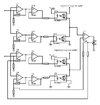
it is a volume attenuator that uses 2 pairs of LDRs as you can see in the photo.
the two opamp chains for each LDR pair are used to ensure that as the input signal varies, when the value of a photoresistor increases, the other connected one decreases in synchrony. same thing for the other branch being 2 channels.
the curves of the LDRs are not equal therefore the task of U7 is to vary the output voltage of the opamp chain of the group below to vary the voltage that controls the led of the photocouplers and obtain the same attenuation value of the 2 channels.
it is true that the u7 opamp inputs are on the audio path but having very high input impedance it is irrelevant.
it is a draft that I tried in the simulator but if I don't connect the U7 output to create the feedback of the other opamps it works but not anymore if I connect .
of course everything that comes before is missing but it is not necessary to know it.
what do you think about it ? Can it work if done right?
I thought I'd ask for an opinion on something.
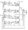
it is a volume attenuator that uses 2 pairs of LDRs as you can see in the photo.
the two opamp chains for each LDR pair are used to ensure that as the input signal varies, when the value of a photoresistor increases, the other connected one decreases in synchrony. same thing for the other branch being 2 channels.
the curves of the LDRs are not equal therefore the task of U7 is to vary the output voltage of the opamp chain of the group below to vary the voltage that controls the led of the photocouplers and obtain the same attenuation value of the 2 channels.
it is true that the u7 opamp inputs are on the audio path but having very high input impedance it is irrelevant.
it is a draft that I tried in the simulator but if I don't connect the U7 output to create the feedback of the other opamps it works but not anymore if I connect .
of course everything that comes before is missing but it is not necessary to know it.
what do you think about it ? Can it work if done right?