Continue to Site

Welcome to our site!

Electro Tech is an online community (with over 170,000 members) who enjoy talking about and building electronic circuits, projects and gadgets. To participate you need to register. Registration is free. Click here to register now.

  • Welcome to our site! Electro Tech is an online community (with over 170,000 members) who enjoy talking about and building electronic circuits, projects and gadgets. To participate you need to register. Registration is free. Click here to register now.

Voltmeter Clock

Status
Not open for further replies.

oliverb

Member
I am adding a "Voltmeter Clock" clock to my Master clock system.

I have used a design by Alan Parekh and have modified it to run 3 voltmeters sourced from Ebay.

Alan's site is here **broken link removed**

I am going to try to modify the code so I can synchronise it with my DCF77 synchronised Master Clock.


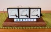
The basic clock (see pic of experimental layout) with modified meters is up and running using Alan's code. I have mounted it on a temp piece of wood for now. The meter dials were drawn up using Turbo cad, the old dials numerals sanded back resprayed white then the new dials transfered on using inkjet transfer parer.

On the finished clock I want to mount the control switches into the base under a perspex flap leaving the dials suspended on metal pillars. The perspex flap will illuminate with the seconds beat. All wiring PCBs and hardware is to be left exposed under a clear perspex cover.

I may also add a small relay to give the clock a tick.


Has anyone on the forum made a clock using meters?

I would love to see your designs.
 

Attachments

  • Voltmeter clock.jpg
    Voltmeter clock.jpg
    224.4 KB · Views: 473
I built one, a couple of years back, it isnt synced to dcf77, I'm in the uk so its synced to msf on 60kc.

Fan001meterclock_zps801618e2.jpg

Its built in an old school ammeter, my designs are rarely flash.
A 'tick' might be annoying, mine has set buttons for hours and mins if theres no msf, and theres 2 leds on the front, one flashes every 3 seconds as a cursor and the other shows if the clock is locked to the msf, there are various error checks for the received time data within the code, which runs on a pic16f88.
If I hadnt have lost the code in a computer crash I'dve added a dht11 and put temp/humidity readings on the meters with the press of a button.
 
Last edited:
hi dr pepper. Great design . Those old school ammeters are really good looking, I saw one a few month back on ebay and was very tempted to bid on it.

If I add a tick I would also add a switch to turn if off. I love the sound of a ticking clock but I know many people hate it.

I am also in the UK (Surrey) but find the MSF signal is not as strong as the dcf77 where I live. I have a feeling the MSF tranmitter has moved further North.
 
Last edited:
Your right, msf has gone to anthorn which is north of the lake district, fairly close to me so I get a really good signal, msf is sposed to cover europe so you should be able to get it, but with it being vlf tends to be affected by all kinds of things.

I have a dcf receiver but havent got eound to writing the code to decode it yet, the good thing about dcf is that unlike msf they dont turn it off for maintenance.

I have built a few odd ball clocks using nixies, dekatrons and other junk.
 
Another one thats on my bench here at work:

AFS.jpg

Its a pendulum clock, the display is a single 7 seg that swings as the weight, and the 'drive' is a hard drive voice coil read head assy jigsawed from a scrap hdd.

Causes plenty of interest.

This one is simple so could be a candidate for a dcf77 mod, theres plenty of room/power in the pic16f88 for it.
 
Last edited:
I had an old BT pulse clock with a long pendulum that drove a BCD display. I never thought about a display in the pendulum before.

On a conventional clock I suppose you could use the pendulum suspension as your power feed by cutting it in 2 and insulating it.
Fit the display to the front of the pendulum bob and the circuit hidden on the back. The timing could be driven by the swing of the pendulum by fitting a hall effect transistor on either side of the pendulum and magnets on the case sides.

If you use a grandfather clock pendulum it would give you a 1 second swing and make the display nice and easy to read.

Sounds like a project for the future..................................................
 
I have a pic programmed up ready for such a device, the pic also has a pwm output to drive a fet as a switch mode supply for powering a single nixie.

One of those projects that only got started.

Nifty idea about connecting power to the display board, I used the allready existing flexible pcb that goes to the read head, its been swinging for months now with no problems, the clock keeps its own time via a 32kc xtal and the pic's timer1, and is surprisingly accurate for something untrimmed about 2 or 3 secs a week.

Heres a nixie I built into a girder (yes I know), seconds is done by a bargraph, this one tells you the date (via msf) and temp/humidity too, theres also a dekatron pendulum on the far right.

003.jpg
 
Last edited:
Hi dr pepper. Another great idea. Do you have any videos of your clocks working?

Here is the You Tube link https://youtu.be/0gSPxQY-dOk to the Simpson clock my clock is based on.

I am just using the circuit (with modded code) and my own display.
 
Despite being into this kind of thing and writing my own code I dont have any video recording gear, except for a steam powered mobi phone, and I'm sure I'll be totally hopeless at presenting anything so nope sorry no vids worth watching.
In fact I've posted some pics including those above on nixie clock sites, and had virtually zero response, these days its all down to the way its presented, not so much what it is.
 
I have finished my Voltmeter clock at last. I had to convert Alan's code to the new version of Picbasic Pro and then add a bit of code to sync it to my master clock. It now keeps perfect time.
Here's a pic
g9QZ4m
https://flic.kr/p/g9QZ4m

and an animation showing sync on 30 sec master clock pulse


and normal running
 
Last edited:
Nice, you did a couple of finer touches that I couldnt be bothered with on mine.
I'd like a chime, I'd thought about a electro/mechanical westminster.
My design uses the same meters, since then I've aquired some 270 degree ones, when I get round to it I'll fit them.
Since msf moved to anthorn I dont seem to be able to get a reliable signal.
Thanks for the update.
 
I have finished my Voltmeter clock at last. I had to convert Alan's code to the new version of Picbasic Pro and then add a bit of code to sync it to my master clock. It now keeps perfect time.
Here's a pic
g9QZ4m
https://flic.kr/p/g9QZ4m

and an animation showing sync on 30 sec master clock pulse


and normal running

I like the sound effects. Was it done on a PIC?
Gonna build one when I have plenty of time...

Allen
 
Hi Allen. Sound is via an ISD1730 chip. I used a kit from Sure electronics from ebay. I recorded the chime from my Longcase clock and played it into the Voltmeter clock audio jack. My master clock pulses out the hours to my Longcase electro mechanical chime and also a relay in the voltmeter clock to chime out the sample through a tiny speaker. The sound is nowhere near HIFI quality but is fine for a very small chime in a room where you don't want the chime to be too distracting. Both clocks chime out together from different parts of the house and sound fantastic together. There are more details on my Master clock site here . The sounds on the animation are all added in from recordings from my master clock system.
 
Status
Not open for further replies.

Latest threads

Back
Top