Continue to Site

Welcome to our site!

Electro Tech is an online community (with over 170,000 members) who enjoy talking about and building electronic circuits, projects and gadgets. To participate you need to register. Registration is free. Click here to register now.

  • Welcome to our site! Electro Tech is an online community (with over 170,000 members) who enjoy talking about and building electronic circuits, projects and gadgets. To participate you need to register. Registration is free. Click here to register now.

Voltage tripler with PWM signals

Status
Not open for further replies.
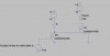
Hi there, I'm having a problem tripling the voltage of a PWM signal, I need to convert 3.3 in at least 9.9V but I'm having a tough time in simulating that in LTSPICE, I can only get it to work for a SINE wave signal and even then the voltage doesn't even reach 9.9V but rather about 8.5V.
What am I doing wrong and is there a way to make this work for Pulse signal?
I'll attach the image of the circuit and result.
Thank you

EDIT: I've realized the voltage wasn't reaching the 9V because I was using diodes that dropped significant voltage while conducting, if I use Schottky diodes the result will be much better. (The question for the Pulse signal remains)
 

Attachments

  • tripler_ltspice.jpg
    tripler_ltspice.jpg
    468.9 KB · Views: 162
  • active_load_control.asc
    1.9 KB · Views: 165
Last edited:
A multiplier circuit of that type builds up a DC voltage and can't preserve a PWM waveform, if that's what you are hoping for.
 
I don't plan to do that, forgot to mention that PWM signal is supposed to be rectified and transformed into a DC voltage, I was using an RC filter before I realised I needed a higher voltage but if this simulation worked with a PWM signal I wouldn't need that right? The question now is why doesn't it work when I use a Pulse?
Thank you for your answer.
 
You've probably just got the pulse parameters set up wrongly in the voltage source - could you show us the voltage source dialogue with the settings you're using?
 
I just configured the pwm to always be on so that he would admit the maximum voltage, I know the rise and down times aren't 0 but for simulation purposes wouldn't it work?
Picture in attachment.

Also I didn't mention that the purpose of the resulting DC voltage is to drive a MOSFET, the maximum voltage I can output with the PWM is 3.3 in my case but the MOSFET needs almost up to 10V in its gate to control the current going through a load.
 

Attachments

  • tripler_ltspice_pwm.jpg
    tripler_ltspice_pwm.jpg
    251 KB · Views: 138
needs almost up to 10V in its gate to control the current going through a load.
Do you have a supply higher than the 3.3V? What powers the 3.3V regulator? Then a simple one transistor amplifier will work.
Look up "logic level MOSFET". They have a lower turn on voltage.
 
Ah, so there's you're problem. It won't work with DC - an AC (or pulsed DC, between 0V and +something) is required to drive a charge pump like this. Try a 50% duty cycle for a start.

Are you hoping to get a continuously-variable DC voltage (0-10V) by varying the PWM duty cycle, because I'm afraid that won't work (at least, not very well). The trippler will tripple the peak voltage of the PWM, not its average voltage. You will, however, be able to vary the maximum current available by varying the PWM duty cycle so if you load the output with a resistor to ground, you may be able to get the desired effect.
 
Do you have a supply higher than the 3.3V? What powers the 3.3V regulator? Then a simple one transistor amplifier will work.
Look up "logic level MOSFET". They have a lower turn on voltage.

I was trying to avoid using an extra external supply, 3.3 is the supply voltage of the MCU i'm using, the MSP430, since all the devices I require can be fed with 3.3 that would save me the trouble. I suppose I could look for a lower gate voltage driven MOSFET, but it has to be a Power MOSFET.

Ah, so there's you're problem. It won't work with DC - an AC (or pulsed DC, between 0V and +something) is required to drive a charge pump like this. Try a 50% duty cycle for a start.

Are you hoping to get a continuously-variable DC voltage (0-10V) by varying the PWM duty cycle, because I'm afraid that won't work (at least, not very well). The trippler will tripple the peak voltage of the PWM, not its average voltage. You will, however, be able to vary the maximum current available by varying the PWM duty cycle so if you load the output with a resistor to ground, you may be able to get the desired effect.

I just want to test a power supply with an active dummy load, if you look at the first image I uploaded on my original post the whole circuit is there, the NDF10N60Z is a power MOSFET that will control the current going through Rload, V1 simulates a 3V3 power supply I want to test. The reason why I need the DC voltage from the PWM to be greater is just because in my simulations, the load is only reaching the current limit for higher voltages than 3.3 at the MOSFET gate.
 
Why is the NMos switch configured as a source-follower (load in the source side) which requires you to have to get the gate to 3.3V+Vt+Voverdrive to fully turn it on? If you put the load in the drain side of an NMos, then you could find an NMos which can be fully turned on with only 3.3V of gate drive (requires ungrounding the load).

Alternatively, replace the NMos with a PMos, leaving the load between the drain and Gnd. The gate drive is now 3.3V off, and 0V is fully-on provided you get a PMos with a Vt of about -1V.

45.png

The plot shows the current through the three load resistors R1, R2, R3 as a function of the 430 port voltage V(in)
 

Attachments

  • Draft45.asc
    1.5 KB · Views: 112
Last edited:
Hey Mike that would be awesome, can you recommend a Power MOSFET that can be completely turned on at 3.3V, with minimum 20W max power, max Id of at least 5A and with a TO package like 220? (So that I can add a heatsink if I have to).
Also what parameter should I look for in the datasheet that lets me know what voltage it requires to be fully turned on?
Thanks a lot for your explanation that was very helpful.
 
Last edited:
Since you didn't put in a location when you registered for the forum, I don't have a clue about your local suppliers. If I was looking for parts, I would be looking at DigiKey or Mouser. They both have search engines that would help you find parts based on parametric searches.

Power FETs in TO220 packages are getting hard to find. Sometimes easier at surplus dealers like Alltronics or the Goldmine.

Almost any NFet with a Vth of < 1.5V, with an Ron < few 10s mΩ should work. Likewise, PFets with a Vth of ~ -1V. The ones I showed in the sim would work, but might be in surface-mount packages...
 
Last edited:
Also what parameter should I look for in the datasheet that lets me know what voltage it requires to be fully turned on?
You look at the Vgs voltage used to specify the ON resistance.
It should be specified for a Vgs of 3.3V or lower to work in your circuit.
 
Since you didn't put in a location when you registered for the forum, I don't have a clue about your local suppliers. If I was looking for parts, I would be looking at DigiKey or Mouser. They both have search engines that would help you find parts based on parametric searches.

Power FETs in TO220 packages are getting hard to find. Sometimes easier at surplus dealers like Alltronics or the Goldmine.

Almost any NFet with a Vth of < 1.5V, with an Ron < few 10s mΩ should work. Likewise, PFets with a Vth of ~ -1V. The ones I showed in the sim would work, but might be in surface-mount packages...

I'm from Portugal! Actually the ones you used wouldn't work because they have a max power rating of 1.8W, just for this PSU rail I need it to hold 10W of power (I have other rails to test but they're all below that I guess).
Regarding packages, if I chose an SMD package or something like that won't I have issues regarding heat dissipation?

You look at the Vgs voltage used to specify the ON resistance.
It should be specified for a Vgs of 3.3V or lower to work in your circuit.

Thank you I'll look into it!
 
Last edited:
Hey Mike one more thing, I was trying to use your simulation with different MOSFET models but they seem to be locking at 2.7A instead of 5A, I didn't change a thing from your file except for the MOSFET model, what am I doing wrong?
 

Attachments

  • Draft45.asc
    1.7 KB · Views: 107
  • tripler_ltspice_pwm_ndf.jpg
    tripler_ltspice_pwm_ndf.jpg
    250.9 KB · Views: 104
Hey Mike one more thing, I was trying to use your simulation with different MOSFET models but they seem to be locking at 2.7A instead of 5A, I didn't change a thing from your file except for the MOSFET model, what am I doing wrong?

I cant run your simulation because you didn't include your library. I'll guess that the Rds as a function of Vds of your Mos model is much higher than the one I used. Note that the FDR6580 has a guaranteed RDS(ON) = 13 mΩ @ VGS = 2.5 V.

Whatever you use needs to have a low RDS(on) with a gate voltage of less than 3V.


ps: I looked up the NDF10N60, and it is totally unsuitable for this task. It is a very high voltage Vds =600V, and very high Rds(on) = 650mΩ with a gate voltage of 10V!

ron.png

Will you be switching the load on/off as fast as possible when the 430 port pin changes from low to high? At what rate? Are you trying for PWM?
 
Last edited:
Thoughts on using a 12V supply so you can use 'normal' MOSFETs.
I went looking for a switched capacitor power supply and did not find what I wanted. (looking for what is in the 3.3V only RS232 driver ICs) They take 3.3V or 5V and make +/-10V for the driver.

The ADM660 is normally used to make a negative supply when you don't have one. But there is a strange mode where it will make a voltage doubler. Two ADM660s can make a 4x circuit.
1) 3.3V--> 6.6V
2) 6.6V--> 12V
upload_2017-7-7_8-44-22.png

Now with a simple transistor + resistor you can have a 0/12V signal on the gate of the MOSFET.
 
I cant run your simulation because you didn't include your library. I'll guess that the Rds as a function of Vds of your Mos model is much higher than the one I used. Note that the FDR6580 has a guaranteed RDS(ON) = 13 mΩ @ VGS = 2.5 V.

Whatever you use needs to have a low RDS(on) with a gate voltage of less than 3V.


ps: I looked up the NDF10N60, and it is totally unsuitable for this task. It is a very high voltage Vds =600V, and very high Rds(on) = 650mΩ with a gate voltage of 10V!

View attachment 106905

Will you be switching the load on/off as fast as possible when the 430 port pin changes from low to high? At what rate? Are you trying for PWM?

I didn't include the library because this forum doesn't let me. Despite the inadequate specs wouldn't it reach the fully turned on state if you provide that voltage? Because it doesn't... it always stales at 2.5 - 2.7 more or less.

I'm not sure what you mean by turning the load on and off, the idea was to keep it on but control the amount of current that goes through it, that's why I wanted DC voltage to control the MOSFET in the first place. I don't think feeding direct PWM into the MOSFET is going to work for what I want to do, or at least I'm not understanding how it can work... I'm not even sure about what frequency I'll be using, I'm still designing my circuit, I haven't programmed the MSP yet

I'm trying to find a more suitable transistor but I'm finding it hard to find one that has all of the requirements I need and has an available spice model...
 
Thoughts on using a 12V supply so you can use 'normal' MOSFETs.
I went looking for a switched capacitor power supply and did not find what I wanted. (looking for what is in the 3.3V only RS232 driver ICs) They take 3.3V or 5V and make +/-10V for the driver.

The ADM660 is normally used to make a negative supply when you don't have one. But there is a strange mode where it will make a voltage doubler. Two ADM660s can make a 4x circuit.
1) 3.3V--> 6.6V
2) 6.6V--> 12V
View attachment 106906
Now with a simple transistor + resistor you can have a 0/12V signal on the gate of the MOSFET.

What's exactly the difference between using that or a regular voltage doubler with capacitors and diodes?

However, so far the "simple transistor + resistor you can have a 0/12V signal on the gate of the MOSFET" seems the best option... Just to be clear by that you mean what's represented on this circuit I've drawn am I right?
 

Attachments

  • best_sol.jpg
    best_sol.jpg
    170.1 KB · Views: 111
I just configured the pwm to always be on so that he would admit the maximum voltage, I know the rise and down times aren't 0 but for simulation purposes wouldn't it work?
Picture in attachment.

Also I didn't mention that the purpose of the resulting DC voltage is to drive a MOSFET, the maximum voltage I can output with the PWM is 3.3 in my case but the MOSFET needs almost up to 10V in its gate to control the current going through a load.
hmmmmmmm............
Ton = 1 second??
and Tperiod = blank?

use Ton = 0.5 ms and Tperiod = 1 ms
 
I didn't include the library because this forum doesn't let me.
You have to fool the forum software by coming up with an allowed filename extension like ".txt"

Despite the inadequate specs wouldn't it reach the fully turned on state if you provide that voltage? Because it doesn't... it always stales at 2.5 - 2.7 more or less.

No. The On-resistance of the MosFet and the 0.66Ω load resistor form a voltage divider. If the Rds(on) is 0.600mΩ, what is the voltage across the load? What is the current through the load? You dont need LTSpice to answer those questions. To get most of the 3.3V supply voltage across the load, what would the Rds(on) have to be compared to 0.66Ω?

I'm not sure what you mean by turning the load on and off, the idea was to keep it on but control the amount of current that goes through it, that's why I wanted DC voltage to control the MOSFET in the first place. I don't think feeding direct PWM into the MOSFET is going to work for what I want to do, or at least I'm not understanding how it can work... I'm not even sure about what frequency I'll be using, I'm still designing my circuit, I haven't programmed the MSP yet

What is the load? What is it used for? How are you going to create a varying control voltage for the gate? Is the NMOS transistor used as an on-off switch, or are you trying to use it as a linear amplifier, where the current in the load is proportional to a varying voltage created by the MSR?

I'm trying to find a more suitable transistor but I'm finding it hard to find one that has all of the requirements I need and has an available spice model...

Who says you have to have a Spice model to do your design?
 
Status
Not open for further replies.

New Articles From Microcontroller Tips

Back
Top