Continue to Site

Welcome to our site!

Electro Tech is an online community (with over 170,000 members) who enjoy talking about and building electronic circuits, projects and gadgets. To participate you need to register. Registration is free. Click here to register now.

  • Welcome to our site! Electro Tech is an online community (with over 170,000 members) who enjoy talking about and building electronic circuits, projects and gadgets. To participate you need to register. Registration is free. Click here to register now.

Voltage to Frequency Converter

Status
Not open for further replies.
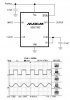
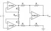
I just built the IA like the figure in the attachment. I'm using Op Amps with GBW 4MHz.

The resistor values for R(Gain) and R are 20KOhms and 10KOhms respectively. The op amps are connected to +12 and -12V supply.

But i can't get the triangle output... Is there anything wrong with it?
 

Attachments

  • ia.JPG
    ia.JPG
    14.4 KB · Views: 242
Last edited:
The schematic looks good. What supply voltages did you use? What voltage are you using for the AD537? I'm assuming the cap in the IA schematic is one in the AD537 VCO.
 
Yup! The timing capacitor is the one attached to the AD537...

I'm using +9V supply for AD537.

As for the op-amp, +12V to V+ and -12V to V-
 
Last edited:
audioguru said:
You can get a "perfect" sine-wave by using a switched-capacitor Butterworth lowpass filter IC. Its oscillator can also be voltage-controlled so that its cutoff frequency tracks the frequency of the VCO.

Hi, thanks for that idea. I'm using MAX7480 which is 8th-Order, Lowpass, Butterworth, Switched-Capacitor Filter...

I manage to get the perfect sine wave output from the VFC square wave. The clock is 100x of its input frequency (generated from function generator).

Is there any method for generating the clock automatically?
If i want any frequency let's say 100KHz, it would able to generate the 10MHz clock........if i want 100Hz, it would able to generate 100KHz clock.

Can it be done through programming? I'm using C... n my project involves parallel port.
 

Attachments

  • Square to Sine.JPG
    Square to Sine.JPG
    36.1 KB · Views: 252
The max cutoff frequency of the MAX7480 is only 2kHz. Other switched capacitor filter ICs can go much higher.
 
How come i manage to get 20KHz of sine wave through 2MHz clock?

In between, can i generate an automatic clock through programming?
 
km said:
How come i manage to get 20KHz of sine wave through 2MHz clock?
I guess your IC was made on a Thursday afternoon. One made on a Monday morning wouldn't go as high.
Actually, the datasheet says that the 2kHz limit is because higher frequencies cause higher noise and distortion. I think a 4th order filter is able to go much higher than an 8th order filter and they can be cascaded to have an 8th order.

In between, can i generate an automatic clock through programming?
I don't know how to "program" a change in a capacitor for its internal clock oscillator. You can feed it any external oscillator you want.

I made a swept frequency low-distortion oscillator with a Phase-Locked-Loop as its clock oscillator which locked to the low frequency from a VCO IC. I used National Semi's switched capacitor ICs (obsolete now) that worked very well up to 30kHz.
 
Is there a more simpler method converting to sine wave? The switched capacitor filter which i used (MAX7410) not really working for lower frequency range.

Can i convert from triangle to sine in these frequency range (0 to 100kHz)?
 
km said:
Is there a more simpler method converting to sine wave?
The simple ways don't filter very well so their distortion is high.

Can i convert from triangle to sine in these frequency range (0 to 100kHz)?
A MAX038 function generator IC makes steps in its triangle wave to make it into a sine-wave. It goes from nearly 0Hz to 20MHz and its sine-wave distortion is about 1% to 3%.
 
Ron H said:
As Audioguru said, a switched-capacitor filter is a good solution, but you have to run your V-F converter at 100X for the clock, and then divide by 100 for the signal. This may not be practical, depending on the desired signal frequency.

Why it is not practical? Is it the 100x frequency is not stable?
 
km said:
Why it is not practical? Is it the 100x frequency is not stable?
100x means 100 times. The AD537 will only go up to 150kHz. This is your fastest clock frequency. You have to divide this by 100 for your function generator output, so your maximum sine wave frequency will be 1.5kHz. I doubt this is high enough for you.
 
Hi, base on the figure. The Output frequency is actually from the AD537 150kHz?

n the input reference frequency is the 1.5kHz (after divide by 100)?

OH! i still thought that the input freq. actually is 150kHz and so tht it can generates an output of 15MHz. I'm wrong.
 

Attachments

  • PLL.JPG
    PLL.JPG
    23.4 KB · Views: 185
To "KM"

Hi newbe here. Forgive the intrusion, but where did you find the circuit using the ad537? I need a method to convert a varying amplitude audio signal into a variable frequency suitible to drive headphones. Thanks.....or anyone with ideas on this. Again thanks, Ron.:confused:
 
Hi newbe here. Forgive the intrusion, but where did you find the circuit using the ad537? I need a method to convert a varying amplitude audio signal into a variable frequency suitible to drive headphones. Thanks.....or anyone with ideas on this. Again thanks, Ron.:confused:
Which circuit?
Why do you want to do what you described?
 
Voltage to freq converter

I've become interested, lately, in looking for gold nuggets along stream beds, with a "vlf" metal detector. They have limited sensitivity. One reason is that they have a tone (about 500 hz I believe) that varies in amplitude when a target is found. That's all fine for coins and large targets, but your ear can only detect changes of 6 db's or so. However, one's ear can detect changes of just a few hz in frequency. I thought I might be able to rectify the tone coming from the "vlf" detector and apply it the Ad537 that was "talked about here on this site. Then maybe run that to an op amp and apply that my headphones. I'm a fair tech, but my engineering skills are limited. Again any ideas would be appreciated. Thanks,Ron.
 
I've become interested, lately, in looking for gold nuggets along stream beds, with a "vlf" metal detector. They have limited sensitivity. One reason is that they have a tone (about 500 hz I believe) that varies in amplitude when a target is found. That's all fine for coins and large targets, but your ear can only detect changes of 6 db's or so. However, one's ear can detect changes of just a few hz in frequency. I thought I might be able to rectify the tone coming from the "vlf" detector and apply it the Ad537 that was "talked about here on this site. Then maybe run that to an op amp and apply that my headphones. I'm a fair tech, but my engineering skills are limited. Again any ideas would be appreciated. Thanks,Ron.
That sounds like it might help. I am a nugget hunter also. Is your VLF machine a Gold Bug II? That's what I have.
 
Re:

I'm using an old thing called a "Big Bud Pro Select 220 D" wow, a mouthfull! Being a southpaw (most metal detectors are very right handed), I've done some easy mods to it and I like the unit very much.
Has anyone seen the Ad537 chip used in a circuit? Thanks, Ron.
 
oy... back to one of the earlier replies: an integrator's instantaneous output slope is proportional to it's instantaneous input voltage.

hence a square wave in gets a 90 degree shifted triangle out. a triangle in gets a 90 degree shifted sine out. if you check the block diagrams on some of the ancient function generator chips you will see they do it this way.

Dan
 
Status
Not open for further replies.

Latest threads

New Articles From Microcontroller Tips

Back
Top